


The PFC reference design is tailored for HEV/EV chargers and high-power SMPS applications, achieving 98.6% efficiency with advanced SiC technology.
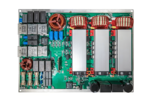
Three-phase Power Factor Correction (PFC) is essential for improving the efficiency and stability of power systems in industrial and commercial settings. It enhances the power factor by aligning the voltage and current phases, thereby reducing reactive power, which does not contribute to actual work. This correction not only helps lower energy costs by reducing demand charges but also increases the electrical system’s capacity, ensures voltage stability, minimizes transmission losses, and aids in complying with regulatory standards. Consequently, PFC is a critical component for optimizing power usage and prolonging the lifespan of electrical infrastructure. The MSCSICPFC/REF5 is a 3-phase Vienna PFC reference design from Microchip tailored for Hybrid Electric Vehicle/Electric Vehicle (HEV/EV) chargers and high-power Switch Mode Power Supply (SMPS) applications.
The reference design incorporates Silicon Carbide (SiC) technology, utilizing our mSIC™ MOSFETs and Schottky Barrier Diodes (SBDs), and achieves an impressive 98.6% efficiency with a 30 kW output. The MOSFET features low capacitances and gate charge, facilitating fast switching speeds due to a low internal gate resistance (ESR). It ensures stable operation even at high junction temperatures, with a maximum rating of 175°C. Additionally, it includes a fast and reliable body diode and exhibits superior avalanche ruggedness. The device is also RoHS compliant, adhering to strict environmental standards. The SBDs are AEC-Q101 qualified, ensuring reliability for automotive applications. It features no reverse recovery, low forward voltage, and low leakage current, enhancing overall efficiency.

The design is optimized for 30 kW applications and features 1200V mSiC diodes and 700V mSiC MOSFETs, which are built to handle high avalanche/repetitive Unclamped Inductive Switching (UIS). It supports a 3-phase 380/400V RMS input voltage at 50 Hz or 60 Hz and offers a 700V DC output voltage. The switching frequency is set at 140 kHz. The PCB layout is meticulously engineered for safety, current stress, mechanical stress, and noise immunity. Control is managed digitally using a dsPIC33CH Digital Signal Controller (DSC), enhancing the system’s overall performance and reliability.
The design challenges include maintaining high efficiency throughout the output power range, minimizing line frequency harmonics across the same range, and creating scalable, high-power-density designs. These objectives are essential for optimizing performance and ensuring the system’s effectiveness and reliability under varying operational conditions.

Microchip has tested this reference design. It comes with a bill of materials (BOM), schematics, assembly drawing, printed circuit board (PCB) layout, etc. You can find additional data about the reference design on the company’s website. To read more about this reference design, click here.
