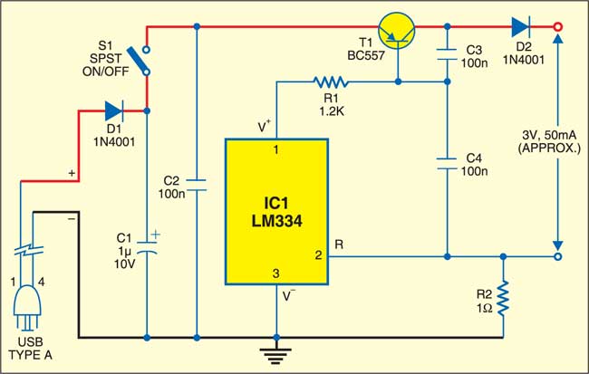
 Plug this PC adaptor circuit into the available USB output port of your PC to get 50mA, 3V DC. So it can be used to recharge, for instance, two NiCd cells (1.2Vx2) of a portable music player system.
PC Adaptor Circuit

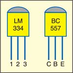
The circuit, built around the popular 3-pin adjustable current source LM334 (IC1), converts the 5V input into approximately 50mA, 3V. Commonly available TO92-style pack is used here. The output current level is maintained through resistor R2. Transistor T1 acts as a current booster.
A standard USB cable (1m long) with a type-A connector at one end is sufficient for input connection. For output connection, you can use a standard DC socket or flying leads with crocodile clips as per your requirements.

Construciton & testing
The circuit can be easily assembled on a veroboard using readily available, low cost components. The USB port of a PC can provide around 100mA current without any problem. Additional components used here are deliberately included to ensure safety and reliability. After you are done with construction, make sure that pins 1 and 4 of the USB cable are connected to the circuit with correct polarity. However, polarity protector diode D1 is used in the circuit for additional protection.
After construction and testing, enclose the circuit in a suitable cabinet.
The article was first publishe din March 2007 and has recently been updated.


