


 Sometimes we need configurable multichannel amplifiers for experiments or for use in offices or schools. Here is a multi mode audio amplifier circuit based on TDA1554Q, configured for multi-mode function with four channel outputs.
Multi mode audio amplifier circuit
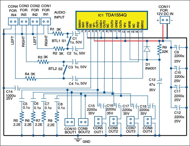
The circuit of the simple 4-channel multi mode audio amplifier is shown in Fig. 1. It has four channels and each channel can provide around 11W over a load of 2-ohms and around 6W over a load of 4-ohms. The circuit will also work with loads of 4-ohms to 16-ohms.
Mode selection
The multi-mode function includes single-channel and bridge-tied load (BTL) modes. These are controlled using switches S1 and S2. In bridge mode, output power can be around 22W on a 4-ohm load with a good heat-sink, power supply and montage.
Gain of each channel is fixed at 20dB in single-channel mode and 26dB in BTL mode.
Input resistance of each channel of TDA1554Q amplifier (IC1) is around 60-kilo-ohm. When two or four inputs are paralleled, resistance is reduced by two or four times. Consequently, input capacitors C1 through C4 should have enough capacity to give the required sound in the low-frequency range.
Download PCB and component layout PDFs: click here
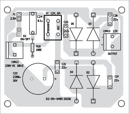
Power supply
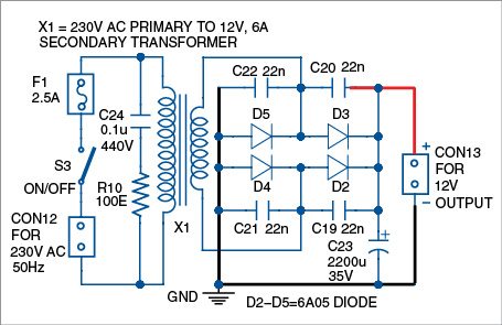
The circuit for the power supply is shown in Fig. 2. Transformer X1 used during testing was rated at 12V AC, 6A. Ratings for X1 can be up to 8A and diodes should preferably be Schotky or other low-drop diodes with 10A rating.
Construction and testing
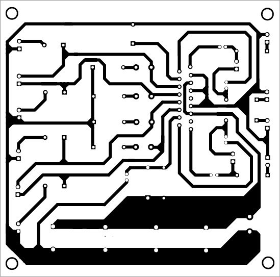
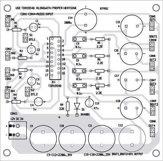
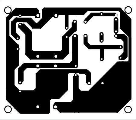
 A single side PCB layout of the 4-channel multi mode audio amplifier is shown in Fig. 3 and its component layout in Fig. 4. An actual-size PCB pattern for the power supply is shown Fig. 5 and its component layout in Fig. 6.
After assembling the circuit on the PCB connect 12V supply from CON13 to the amplifier circuit at CON11. Switch on the circuit by closing power switch S3. You can give audio inputs from any audio source like an MP3 player, laptop or DVD player to CON1 through CON4.
If switches S1 and S2 are open, the circuit is in single-channel mode. If closed, these are in BTL mode. The 4-channel outputs are available at CON5 through CON8. Outputs for BTL mode are available at CON9 and CON10. Switch S3 and fuse F1 should be mounted on the rear panel.
It is recommended to use 2-way panel-mount spring-loaded speaker connectors for CON5 through CON10 and 3.5mm stereo female panel-mount connectors for CON1 through CON4.
Feel interested? Chcek out other electronics projects.

Can i make this circuit to home theatre system. what are the changes required?
Here is the reply to Abhijit from author Petre Petrov.
“Yes, you can use that circuit as an end (power) stage(s) of audio system with four channels. if you use two boards you can have up to eight audio channels. In home application 5-10 Watts of power per channel is more than enough. If you are in need of more power per channel you can use the channels in parallel but please note the polarity (the phase ) of the signals. Please see the data sheet.
Please pay attention to the connection of the loudspeakers.”
Congratulations; please accept my suggestion to add:
USB socket & audio St socket; so can be used to power a Bluetooth receiver and get music from a smartphone
That’s all
Figueiredo
How to connect volume control in this circuit