


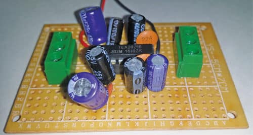
 Here is how we can build a 5W stereo audio power amplifier based on TEA 2025 IC and two potentiometers for left and right volume controls. Its power output is 2.5W on the left and right channels each with a 12V DC power supply. The author’s prototype is shown in Fig. 1.
Circuit and working
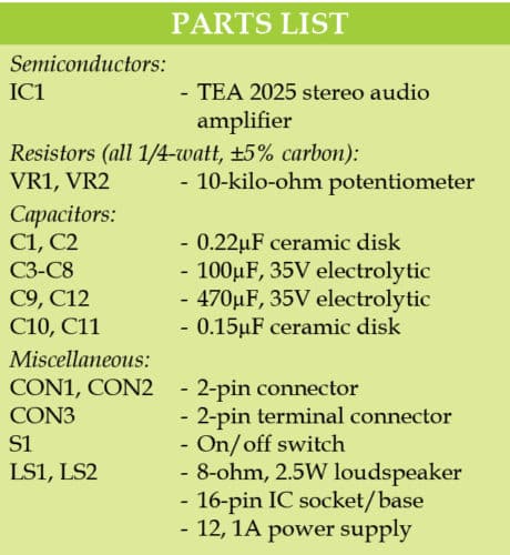
The circuit diagram of the 5W stereo audio amplifier is shown in Fig. 2. It is built around TEA 2025 (IC1), two 10-kilo-ohm potentiometers (VR1 and VR2), two 8-ohm, 2.5W loudspeakers (LS1 and LS2) and a few other components.
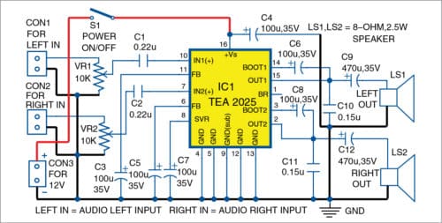
TEA 2025 is a 16-pin IC, whose pin 16 is connected to positive terminal of +12V supply. Electrolytic capacitor C4 is connected between +12V and ground. Pins 4, 5, 9, 12 and 13 of IC1 are grounded.

Left audio input (left in) and right audio input (right in) are connected across connectors CON1 and CON2, respectively. Left and right audio inputs are further given to inputs of TEA 2025 via VR1 and VR2, and C1 and C2, respectively. Audio is amplified by IC1, and its left and right audio outputs are available across LS1 and LS2, respectively.
Construction and testing
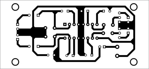
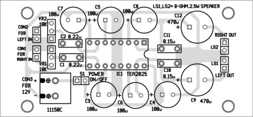
A PCB layout of the 5W stereo audio amplifier is shown in Fig. 3 and its components layout in Fig. 4. Assemble the circuit on the PCB and solder 16-pin IC socket for IC1 on it. Connect 12V DC across CON3. Connect audio left input across CON1 and right input across CON2 from an audio source like a PC, laptop or cellphone.
Download PCB and component layout PDFs: click here
Alternatively, you can use Veroboard of size 5cm x 7cm to build this amplifier.
Place all passive components like electrolytic and ceramic capacitors as given in the circuit diagram and solder these on the PCB. VR1 and VR2 are connected to inputs (right and left) of the amplifier on the PCB.
Calibration and adjustments
Connect a 12V DC or battery to the amplifier. Take two loudspeakers (8-ohm, 2.5W) and connect these at LS1 and LS2, as shown in Fig. 4. Now, turn the wipers of both the potentiometers (10-kilo-ohm) to middle position.
Take a metal screwdriver and gently touch at left input. You will hear a humming sound coming from the left speaker, which means that the left channel of TEA 2025 is working.
Similarly, touch the right input terminal and you should hear a humming sound coming from the right speaker.
You can also use a signal generator to calibrate the prototype. Simply connect output (say, 1kHz) of the signal generator to left and right inputs of the amplifier. You will hear a loud audio tone coming from the loudspeakers, which means the amplifier is working well. Adjust volume controls (VR1 and VR2) as per taste and requirement.
Raj K. Gorkhali is an electronics hobbyist
Need bluetooth motherboard circuit and parts.
How to install LED light strip what are needed to connect LED strip with switch