


The reference design powers RGB LEDs in portable projectors, providing efficient current control, fast response, and precise color management for various applications.
A 6A RGB LED driver is a critical component in high-performance lighting and display systems, providing precise control and power management for RGB (Red, Green, Blue) LEDs. By delivering a high current of up to 6A, this driver ensures optimal brightness, making it ideal for applications such as projectors, large-scale displays, and advanced lighting setups. Its ability to regulate power efficiently, manage heat, and provide smooth color mixing and dimming is essential for achieving accurate color representation, stable operation, and energy-efficient performance in modern electronic devices. The reference design from Analog Devices (ADI) is for a 6A step-down LED driver used in a portable projector. It is built around the MAX16821, a PWM high-brightness LED driver. The circuit is designed to drive a single LED, and three MAX16821 devices are needed to power RGB LEDs.
The LED driver steps down an input supply voltage of 10V to 15V to provide a constant current to an LED with a forward voltage range of 4.5V to 6V. The step-down converter is implemented using the MAX16821 PWM high-brightness (HB) LED driver. Since the average inductor current is equal to the LED current, the inductor current is regulated to ensure a steady current is delivered to the LED. The switching frequency is set to 300kHz, controlled by resistor R6 (200kΩ).

The system operates with two control loops: the inner current loop and the outer voltage loop. The inner current loop controls the inductor current based on the output from the outer voltage loop, while the outer voltage loop programs the inner loop to regulate the LED current.
An op amp takes a simple input voltage between 1.1V and 2.8V to control how much current flows to the LED, ranging from 1.5A to 6A. When the LED needs 6A of current, the op amp adjusts its output to about 20mV, which is just enough to drive the MAX16821.

Theresistors help measure and adjust the current, making sure the correct amount flows to the LED. They work together to set a reference voltage of 100mV at the input when the LED current is at 6A.
The design needs the LED current to rise and fall within 1 microsecond (1μs) when the LED current is set to 6A during PWM. To achieve this, a small output capacitor and a larger inductor are used to keep the LED current ripple within limits. When the LED current is set to 6A, the MAX16821 keeps the inductor current steady at 6A.
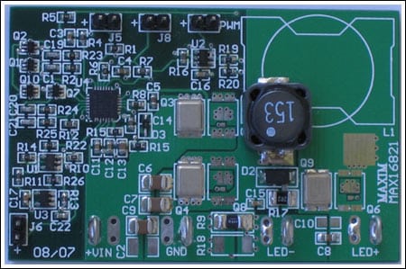
ADI has tested this reference design. It comes with a bill of materials (BOM), schematics, assembly drawing, printed circuit board (PCB) layout, and more. The company’s website has additional data about the reference design. To read more about this reference design, click here.
