 For testing of microcontroller-based circuits, you need two test jigs: One for generating the desired bitstream to serve as the input to the device and the other to display the processed output. Here is a simple but effective arrangement for producing the desired bitstream and display. It has been successfully used for fault finding.
There are two circuits: 8-bit generator and 8-bit display. As shown in Fig. 1, the eight connectors (CON0 through CON7) are set to either logic high (1) or logic low (0) to generate the desired 8-bit stream. Middle terminals of these connectors are connected to the inputs of CD4050 buffer ICs (IC1 and IC2). The other two terminals of the connectors are connected to +5V and ground, respectively.
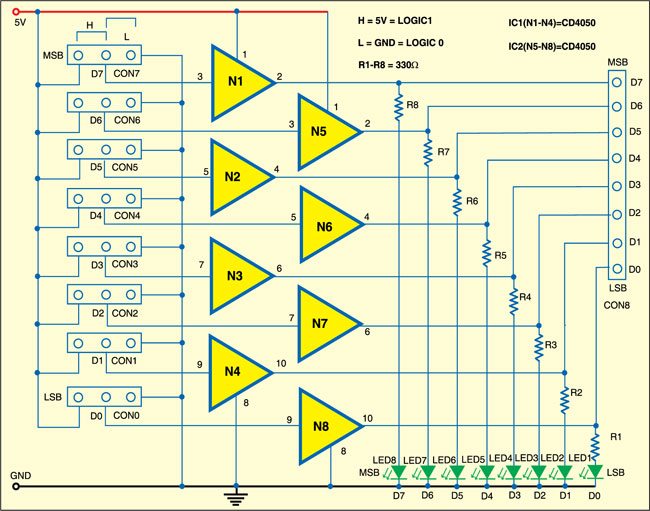
Setting the data is simple. For example, to set the data as 1001 1100, using jumpers, set connectors CON2, CON3, CON4 and CON7 to 5V to make the respective bits high (logic 1). The corresponding LEDs (LED3, LED4, LED5 and LED8) glow to indicate the same.

Similarly, set connectors CON0, CON1, CON5 and CON6 to ground to make the respective bits low (logic 0). The corresponding LEDs (LED1, LED2, LED6 and LED7) don’t glow. The bitstream so generated is available at connector CON8, which can be used as input to the microcontroller under test.
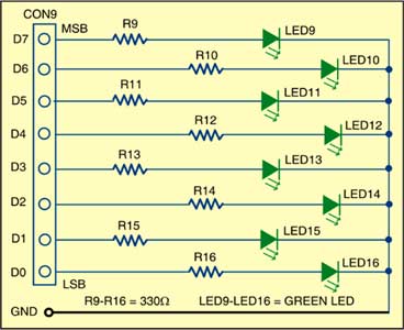
Fig. 2 shows the 8-bit display unit. To display the processed output, pins of the microcontroller are connected to connector CON9. LEDs (LED9 through LED16) indicate the logic status of the eight bits.

Assemble the 8-bit generator and display circuits on two separate general-purpose PCBs. Connect the LEDs in sequence so that you can read the data easily.