 Certain industrial controls require accurate switching operations. For example, in case of a foot-switch for precise drilling work, even a small error in switching may cause considerable loss. This low-cost but accurate foot-operated switch can prevent that.
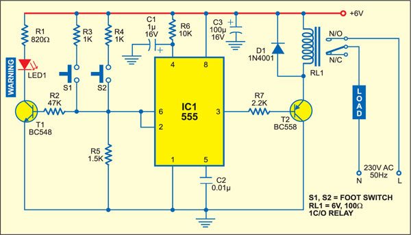
IC NE555 is wired in one-shot mode. Its output pin 3 goes high only when both switches S1 and S2 are pressed simultaneously. You can release any one of the switches without changing the output state. When you release both the switches, the output goes low.

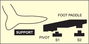
The switches are placed under a foot paddle as shown in Fig. 2. LED1 is used as a warning indicator. If either S1 or S2 gets pressed erroneously, LED1 blinks to warn the operator. The operator can then withdraw his foot in case of a mistake or depress the other switch also to trigger the circuit. LED1 is to be mounted on the operator’s desk.
The circuit operation is simple. Resistors R2, R3 and R4 form a voltage divider. IC NE555 has two comparators, a flip-flop and power output section built into it. Pressing either S1 or S2 puts the input voltage between the upper comparator (2/3Vcc) and the lower comparator (1/3Vcc). Thus, it has no effect on the state of the internal flip-flop of IC NE555. Pressing the two switches simultaneously sets the flip-flop and the output of NE555 goes high. Transistor T2 energises relay RL1 for driving the load.

Releasing any of the switches brings the comparator voltage back to the initial level inside NE555 and it has no effect on the state of the flip-flop. Releasing both the switches brings the input level with respect to ground below the low trigger level, and thus it resets the output.
Use of the voltage divider results in stable operation over the entire permissible supply voltage range. The RC circuit at pin 4 provides power-on reset.
When only S1 is pressed, R3 (1 kilo-ohm) is less than R5 (1.5 kilo-ohms) and IC1 is not triggered. However, transistor T1 (BC548) gets forward biased and LED1 glows. When both S1 and S2 are pressed, the effective resistance between +Vcc and pin 2 of IC1 is about 500 ohms, which is less than R5 (1.5 kilo-ohms), and IC NE555 gets triggered.


