


This project describes how to make the alarm clock radio in Arduino. The main feature of this project is that it will display date, time, will Alarm on the desired time and it has a function of radio too. This is a simple project and can assemble within a few bucks. I took inspiration for this project from Mr. Tiziano Bianchettin, an Italian friend but I have changed both hardware and software as per my requirement. I would like to thank you from the bottom of my heart to Mr. Tiziano Bianchettin for the help and guidance during this project.
Construction
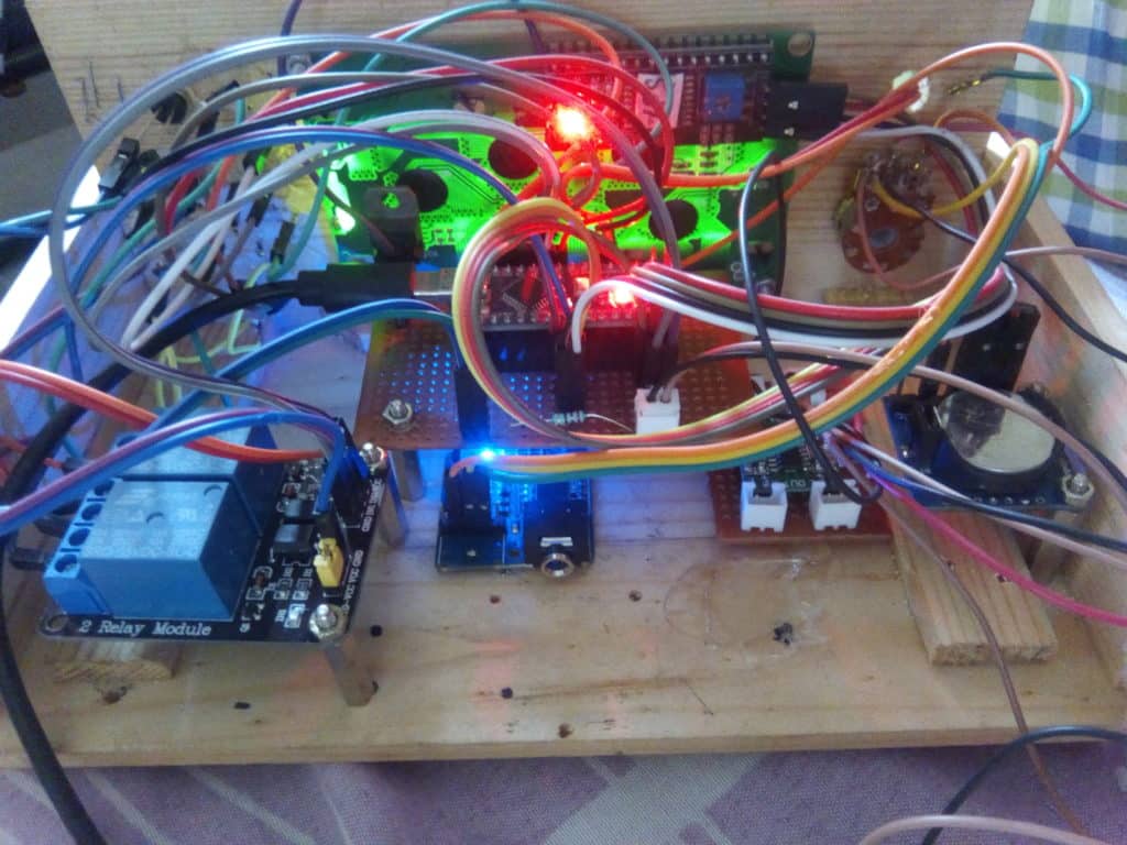
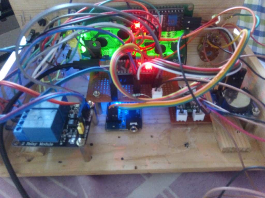
In this project, I have used RTC module, Radio Module and LCD Display all are interfaced via I2C protocol. I²C stands for the inter-integrated circuit and refers to a communication protocol that we are going to use to communicate between our Arduino and devices. I have only entered 5 preset stations in code, but you can increase, it by changing the code a bit.
There were 2 Relay modules Used in this project, those are the Single channel relay module and a 2 channel relay module. Single-channel relay module switch on, off the amplifier and radio module TEA 5767 once Switch S6 pressed.

The 2-channel relay module is connected with switch S7, this is an “OK / ENTER” switch for the radio. This S7 switch has to press each time we change the station. This 2 channel relay used in this circuit because During the construction of this project I found there were some permanent noise/ disturbances present in the audio stage of radio which I tried to fix via code but unable to remove (Assuming I2C Communication signals for Clock present as noise ) so I introduced this relay mechanism with a switch to avoid that annoying noise from audio stage.
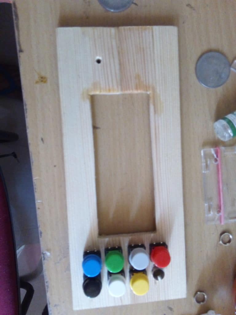
There are 7 tactile switches are using for edit date, time, Manual tuning of radio, selection of pre-set channels of radio, on-off and edit alarm and on-off radio functions.

Note: This project requires 5v 2A minimum to work and failure on giving this current rating will result in non-function of the circuit.
Functions of Switches as follows
- S1: Menu (Time Date Edit Function )
- S2 & S3: + and – function (+ and – of Date, Time and Manual tuning of radio)
- S4: Alarm On & OFF
- S5: Pre-set Channel change switch for Radio
- S6: On & Off Switch for radio.
- S7: OK or ENTER switch for radio (need to press each time while changing the channel of radio)
How to adjust Alarm Time
- Push S4 to switch on alarm mode
- Press and hold S3 and then press S2 to enter alarm time edit mode and adjust alarm time by pressing s2 and s3 again then press s1 to save the alarm time
Input & Output Ports of Arduino
- S1 – D6
- S2 – D7
- S3 – D8
- S4 – D9
- S5 – D5
- S6 – D11
- S7 – On switch for 2 channel relay
- Buzzer – D10
- Gate Of MOSFET IRFZ540 – D12
- LED –D13
Parts Lists
- Arduino Nano /Uno
- 20 X 4 LCD Display (I2c LCD display)
- RTC Clock Module (having I2C interface)
- TEA 5767 module
- PAM 8403 (5W Amplifier)
- Micro USB extension port
- Mini USB cable
- 2 Channel relay board (Having Optocoupler)
- 1 Channel relay board (Having Opto Coupler)
- 5v – Buzzer
- 5W, 4 Ohm speaker X 2 Nos
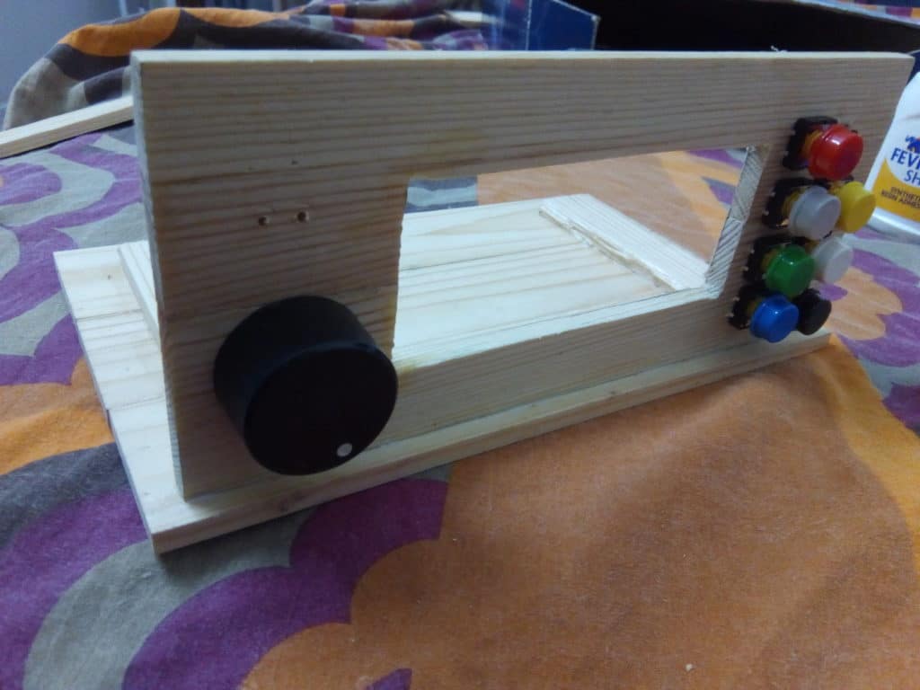
- Big Tactile Switch with caps 7 Nos.
- Led – 1
- R3- 220 Ohm resistance
- R1&R2 – 10K
- Mosfet – IRFZ540
- 5v, 5A power supply adapter
- DC Female input socket
- Common PCB board
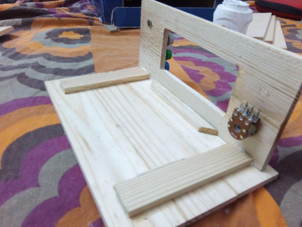
- POT – 10 K
Download Arduino code and Library files from this link: click here
Circuit Diagram
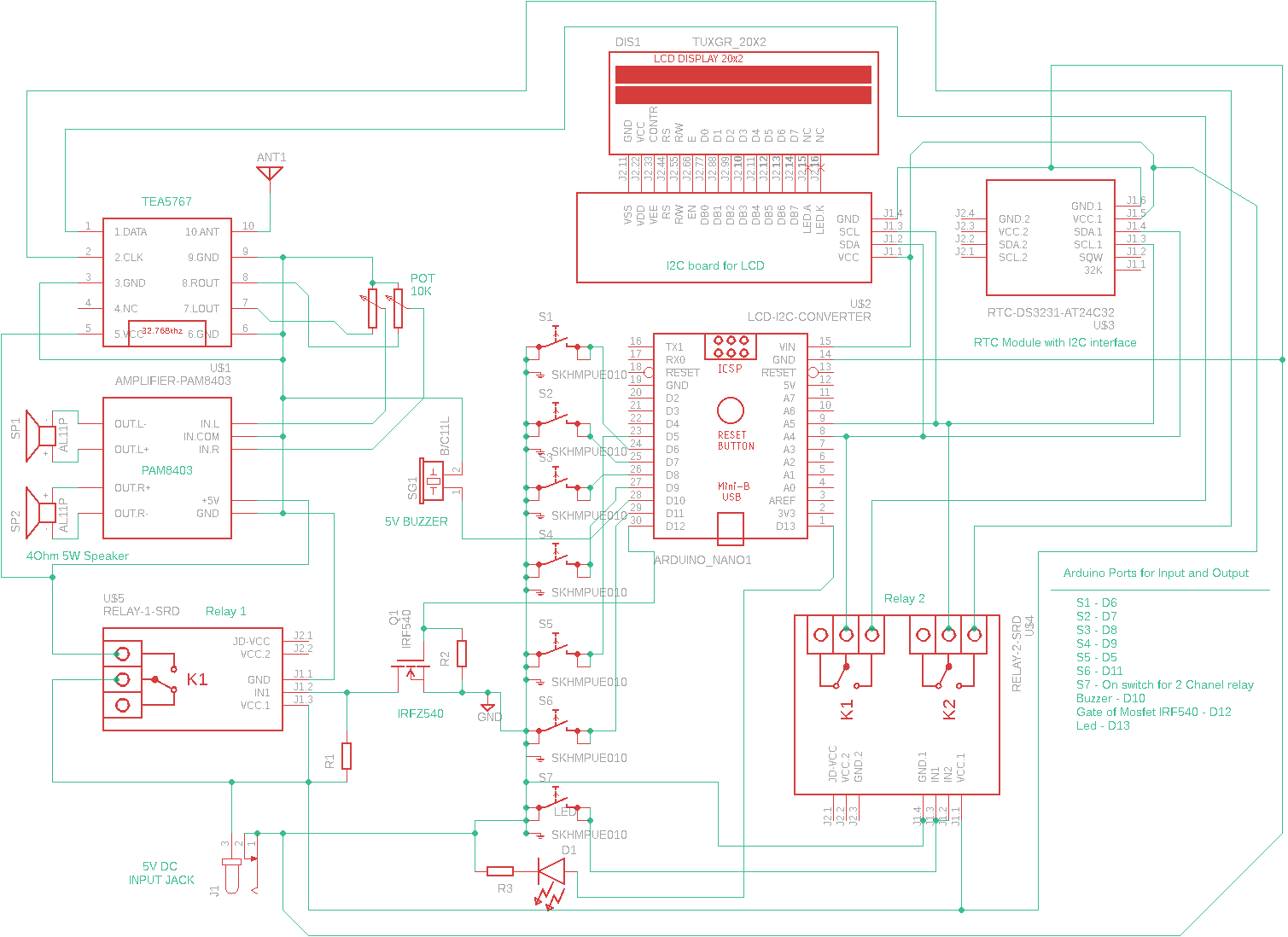
Download PDF of Circuit Diagram: click here
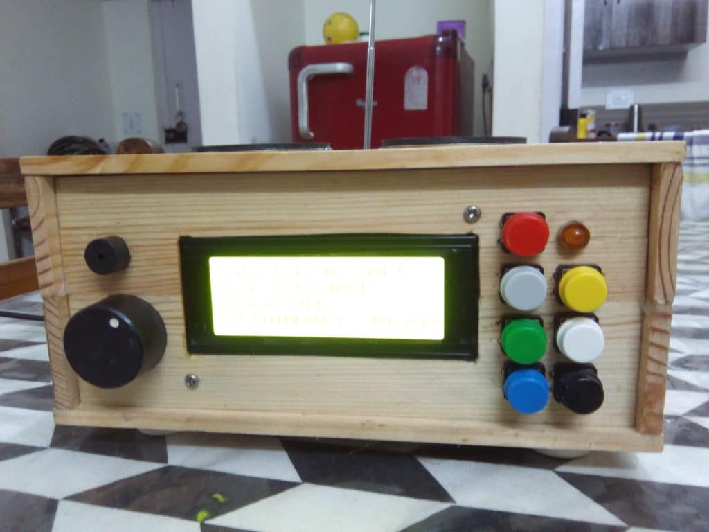
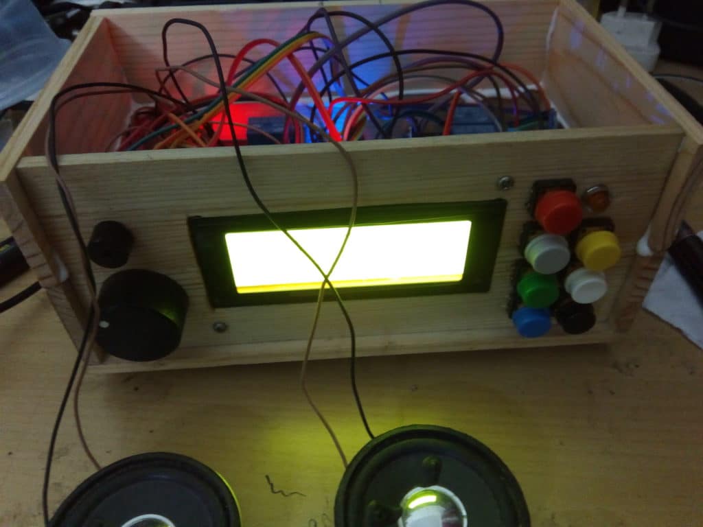
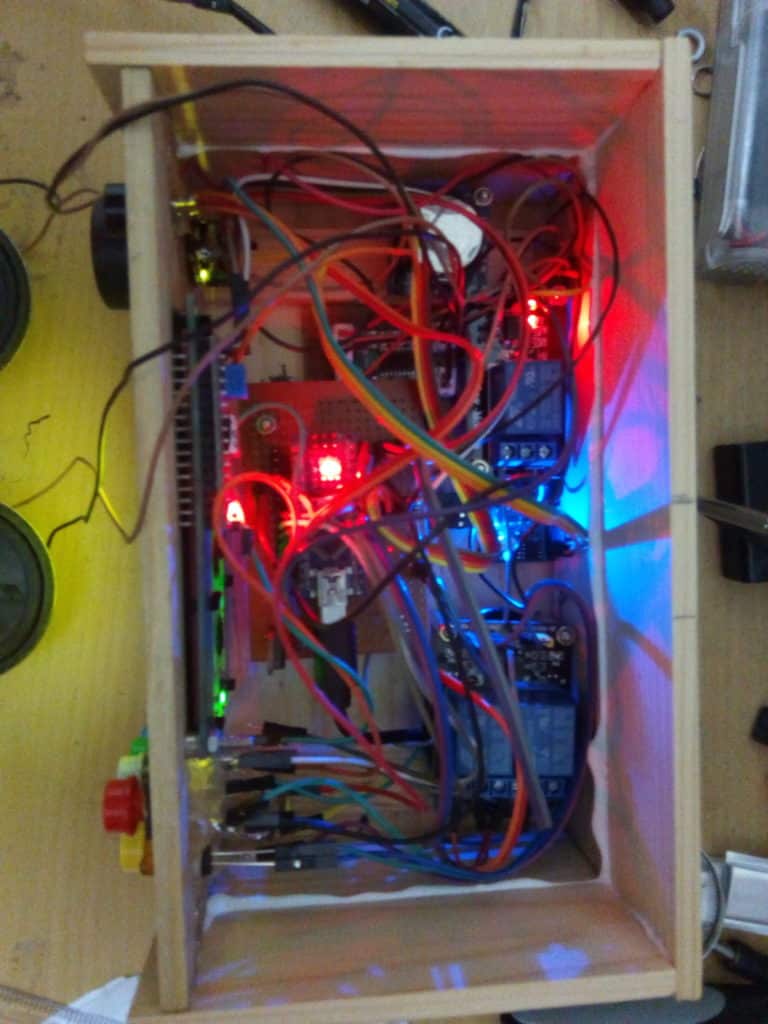
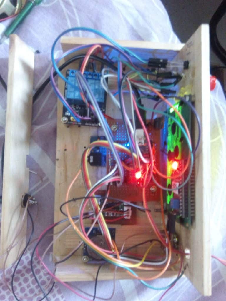
Prototype


Check more such tested Arduino projects.
Gireesh Kumar is an MSc. Electronics graduate residing in Visakhapatnam. He is an enthusiast in electronics. His hobbies are making circuits, Arduino programming and Dxing

Dear Vgood morning
I am Bukhari, really you are doing impressive work please keep it.
The download link is not working, error 404 is coming once we trying to download.
kindly if you do not mind can you send us the schematic and code file via email.
will be very thankful for your kind help.
We have added a new zip file, you can download the files now.
CIRCUIT PDF LINK OF DIAGRAM WAS BROKEN AND REPAIRED NOW ITS WORKING . THOSE WHO TRYING THIS PLEASE SEND A LINK HERE
PDF LINK OF CIRCUIT DIAGRAM WAS BROKEN AND REPAIRED NOW ITS WORKING . THOSE WHO TRYING THIS PLEASE SEND A LINK HERE
Please feel free to contact me on any clarification on this project My email id is [email protected]. I request to share the photographs/ videos of your version after the completion of it.
Code and diagram not available in link