


 This LED Night Lamp uses a 1.5W LED module operated on a 12V DC power supply. Here, an L14F1 phototransistor works as a sensor. When there is sufficient light falling on the sensor, LED remains off; but when there is dim or no light, LED automatically starts glowing. The author’s prototype is shown in Fig. 1.

Circuit and working
The circuit diagram of the low-cost ambient-light-controlled LED Night Lamp is shown in Fig. 2. The circuit consists of a bridge rectifier (BR1) followed by a filter and a Zener regulator (ZD1). ZD1’s output gives 12V, which is used to drive the main circuit.
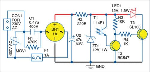
The main circuit consists of an L14F1 phototransistor (T1), which is connected to the base of the BC547 transistor (T2). An SL100 transistor (T3) is connected to the 12V, 1.5W LED module.

When light falls on T1, it conducts and switches on T2. When T2 is switched on, there is 0V at its collector. This switches off T3 and the LED module goes off. When there is no light falling on T1, T2 switches off and 12V is available at its collector. This switches on T3 and the LED module glows. This means, during daytime, the LED module gets automatically switched off, while during night, it switches on.
It may be noted that a step-down transformer is not used here. In this circuit, voltage is obtained through 0.47µF capacitor without much loss. Unlike resistance, there is not much loss in the practical capacitor because current (I) leads voltage (V) by almost 90 degrees.
 Construction and testing
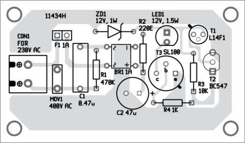
A PCB layout of the low-cost ambient-light-controlled LED Night Lamp is shown in Fig. 3 and its components layout in Fig. 4.

Download PCB and Component Layout PDFs: Click here
Assemble the components on the PCB as per the circuit diagram and hook the circuit to AC mains. After connecting the circuit to AC mains, test it by blocking the ambient light falling on T1. If the LED module is switched on and off by blocking and unblocking ambient light with your hand in front of T1, it means night and day conditions are being simulated. The circuit is now ready to use.
Daniel Antonio Figueiredo is a retired scientist/engineer from National Institute of Electronics & Information Technology (NIELIT), the government of India. He worked in the private sector in various capacities before joining NIELIT
Dear Sirs,
the link for the PCB and Component Layout PDFs is not correct.
The downloaded file Pic.zip contains PCB with code: 9609H instead the correct 11434H.
Please can you fix this link?
Kind Regards
Mitsos
Please refresh the page and download.