


 Unlike current or voltage measurement, the measurement of power is somewhat inconvenient as power is the product of voltage (V) and current (I) flowing through a dissipative circuit.
In a linear-moving coil meter, the deflection of the pointer is proportional to the current flowing through the meter. It is also proportional to the duty cycle of the current waveform. The net deflection is proportional to the product of duty cycle and the magnitude of current. Using this principle, the power in a circuit can be measured. The degree of deflection of the pointer is proportional to the product VI, giving the meter the property of a power meter.
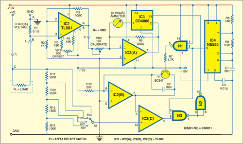

The figure shows the circuit of an analogue wattmeter. This meter makes three connections (A, B and C) with the test circuit. The current through the test circuit is sampled by measuring the voltage drop across a small resistor (R1) such that its introduction does not affect the current in the test circuit significantly. After amplification of this voltage, it is made to generate a constant current, the magnitude of which is proportional to the voltage drop across series resistor R1.
The voltage that drives test load RL is sampled through an attenuator circuit and fed to a comparator that compares it with a ramp voltage. The higher the supply voltage of the test circuit, the higher the point in the ramp at which the comparator fires. Thus pulsewidth modulation becomes proportional to the value of the sampled voltage. The output of the comparator along with the logic gates is used to modulate the flow of current through the meter, making its deflection proportional to VI in the test circuit.

The values shown in the circuit correspond to a meter capable of measuring (5V, 10V, 20V, 50V)x500 mA, or 2.5W to 25W. By selecting an appropriate value of R1, it is possible to accommodate higher currents and thus higher power.
IC1, which is configured as a non-inverting voltage amplifier, is used to amplify the voltage across R1. IC2(A) generates a constant current (Ic = Vi/Rc) that is proportional to the voltage output of IC1. Electronic switch CD4066 modulates the current through the meter, causing variation of the duty cycle proportional to the voltage of the test power circuit.
The ramp duty-cycle generator consists of ramp voltage generator IC2(B), comparator IC2(C), timing oscillator NE555 and logic gates. The voltage of the test circuit is attenuated and directly fed to the non-inverting input of IC2(C). NE555 is set to oscillate at a moderate frequency of around 800 Hz. The ramp needs periodic discharge of capacitor C2 for repetitive production of ramp profile. This is done by transistor T1.
For null offset, use a 10-kilo-ohm multiturn trimpot VR1 with 15-kilo-ohm resistors R4 and R5 on either side terminals of the wiper. Eliminate the offset when power is not applied to the test circuit by measuring voltage Vi with a 0-200mV digital voltmeter. Adjust VR1 until the reading on the digital voltmeter is 0.00. It is easy to adjust calibrating resistor Rc by measuring known power parameters like 5V and 400 mA. R6 is the shunt resistor whose value is to be chosen such that the meter has a full-scale deflection for 5 mA.
