


 Here is a simple anti bag snatching alarm circuit to thwart snatching of your valuables while travelling. The circuit kept in your bag or suitcase sounds a loud alarm, simulating a police horn, if someone attempts to snatch your bag or suitcase. This will draw the attention of other passengers and the burglar can be caught red handed. In the standby mode, the circuit is locked by a plug and socket arrangement (a mono plug with shorted leads plugged into the mono-jack socket of the unit). When the burglar tries to snatch the bag, the plug detaches from the unit’s socket to activate the alarm.
Anti bag snatching alarm circuit
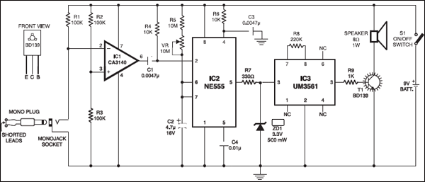
The circuit is designed around op-amp IC CA3140 (IC1), which is configured as a comparator. The non-inverting input (pin 3) of IC1 is kept at half the supply voltage (around 4.5V) by the potential divider comprising resistors R2 and R3 of 100 kilo-ohms each. The inverting input (pin 2) of IC1 is kept low through the shorted plug at the socket. As a result, the voltage at the non-inverting input is higher than at the inverting input and the output of IC1 is high.
The output from pin 6 of IC1 is fed to trigger pin 2 of IC NE555 (IC2) via coupling capacitor C1 (0.0047 µF). IC2 is configured as a monostable. Its trigger pin 2 is held high by resistor R4 (10 kilo-ohms). Normally, the output of IC2 remains low and the alarm is off. Resistor R6, along with capacitor C3 connected to reset pin 4 of IC2, prevents any false triggering. Resistor R5 (10 mega-ohms), preset VR (10 mega-ohms) and capacitor C2 (4.7 µF, 16V) are timing components. With these values, the output at pin 3 of IC2 is about one minute, which can be increased by increasing either the value of capacitor C2 or preset VR.

Circuit in action
When there is an attempt at snatching, the plug connected to the circuit detaches. At that moment, the voltage at the inverting input of IC1 exceeds the voltage at the non-inverting input and subsequently its output goes low. This sends a low pulse to trigger pin 2 of IC2 to make its output pin 3 high. Consequently, the alarm circuit built around IC UM3561 (IC3) gets the supply voltage at its pin 5. IC UM3561 is a complex ROM with an inbuilt oscillator. Resistor R8 forms the oscillator component. Its output is fed to the base of single-stage transistor amplifier BD139 (T1) through resistor R9 (1 kilo-ohm).
The alarm tone generated from IC3 is amplified by transistor T1. A loudspeaker is connected to the collector of T1 to produce the alarm. The alarm can be put off if the plug is inserted into the socket again. Transistor T1 requires a heat-sink.

Resistor R7 (330 ohms) limits the current to IC3 and zener diode ZD1 limits the supply voltage to IC3 to a safe level of 3.3 volts. Resistor R9 limits the current to the base of T1.
Construction
The circuit can be easily constructed on a veroboard or general-purpose PCB. Use a small case for housing the circuit and 9V battery. The speaker should be small so as to make the gadget handy. Connect a thin plastic wire to the plug and secure it in your hand or tie up somewhere else so that when the bag is pulled, the plug detaches from the socket easily.
The article was originally published in February 2004 and has been recently updated.

Sir we want some equipments in bag anti snatching alarm circuit
Kindly elaborate.
Hello, is it possible for me to order this circuit from you or anywhere else? I don’t have any experience or knowledge on how to build a circuit but would like to use this for my own handbag. Any advice?