


 Most accidents on highways at the night occur due to drivers’ poor vision caused by the continuous exposure of their eyes to the bright light from the headlamps of approaching vehicles. Poor vision is due to exhaustion of the visual pigment in the eyes, which induces sleep to restore the pigment. This anti-sleep alarm keeps you awake.
This circuit keeps you alert by sounding intermittent beeps and emitting flashing lights so as to remind you that you are not in bed but driving a vehicle. It works only at night due to the control of a light-dependent resistor (LDR) based switch.
Anti-sleep Alarm Circuit
The LDR along with two BC548 transistors (T1 and T2) forms the light switch to inhibit the oscillation of IC1 during daytime. As the LDR is exposed to light during daytime, T1 conducts to keep T2 out of conduction. This makes the reset pin (pin 12) of IC1 high to prevent it from oscillating. So the remaining part of the circuit remains in standby mode.

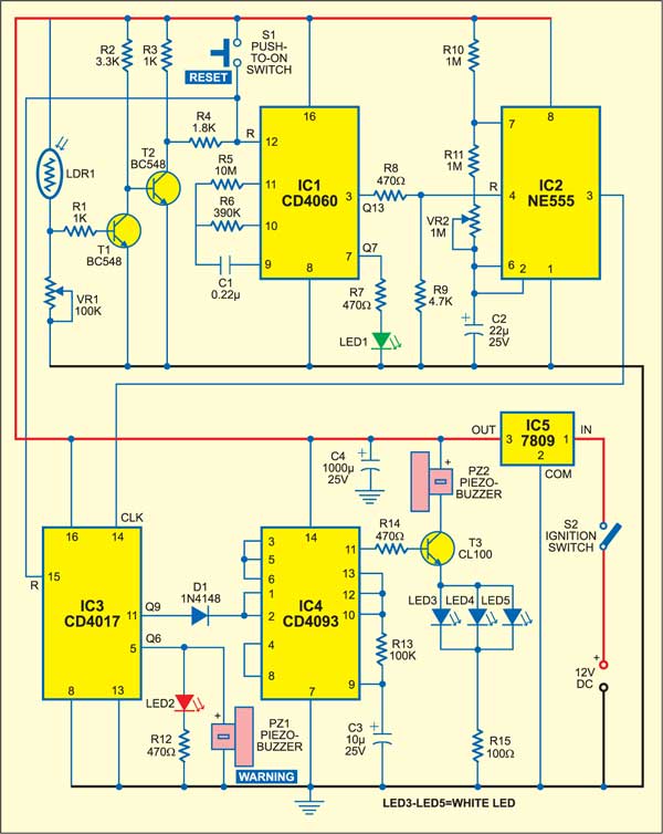
At night, T1 remains non-conducting as the LDR is in dark. Transistor T2 conducts to pull the reset pin (pin 12) of IC1 to the ground. This starts the oscillations of IC1, which is indicated by the flashing of LED1. The internal oscillator of binary counter IC CD4060 oscillates at a frequency based on the values of R5, R6, and C1. Its Q13 output becomes high and low alternatively for 15 minutes each. Using potmeter VR1, you can adjust the sensitivity of the LDR.
Anti Sleep Alarm Working
When the Q13 output of IC1 becomes high, the reset pin (pin 4) of NE555 astable (IC2) becomes high and starts oscillating. For the selected values of R10, R11, VR2, and C2, there will be one pulse every 50 seconds. Using VR2, you can slightly adjust the pulse rate. The pulsed output from IC2 is fed to the clock input of IC CD4017 (IC3).

IC CD4017 is a decade counter with ten outputs, but only one of its outputs is high at a time and all the other outputs remain low. The output from IC2 serves as a clock for IC3. As a result, the Q1 output of IC3 becomes high at the first positive edge from IC2 after 50 seconds. After 6 minutes, the Q6 output goes high and LED2 glows for one minute, and the warning buzzer sounds.
If the circuit is not reset using push-to-switch S1 after hearing the warning beep from PZ1, the counting of IC3 continues and at the end of the 10th minute, the Q9 output becomes high to activate IC CD4093 (IC4).
Circuit Construction
IC4 is wired as a simple oscillator using its two NAND gates 3 and 4. Gate 1 of IC4 is controlled by the status of its input pins 1 and 2. When these pins receive a high output from IC3, the output of gate 1 goes low and the output of gate 2 becomes high. This starts the oscillator built around gates 3 and 4. The frequency of oscillation depends on the values of R13 and C3.
As long as the Q9 output of IC3 remains high (i.e. for 15 minutes), IC4 oscillates and the piezobuzzer beeps and the white LEDs flash with a frequency determined by the values of R13 and C3. Thereafter IC4 stops oscillating and the piezobuzzer and the LEDs turn off for another 15 minutes. The cycle repeats every 15 minutes. This is sufficient to alert the napping driver. IC5 and C4 provide regulated 12V DC to the circuit.
The circuit can be constructed on a perforated board and powered by the vehicle’s battery. The assembled unit should be placed in front of the driver seat preferably on the dashboard. Keep LDR1 away from LEDs to allow it to hibernate at night. The power to the circuit should be tapped from the ignition switch so that the circuit functions only when the vehicle is on the road.
For more such interesting DIY electronics projects, you can check the list of mini projects.
If you face any issues while making this anti-sleep alarm project, then please feel free to ask in the comments below.

and how to test it.?
Kindly elaborate your query.
How to test this ckt??
Hi i need further explaination for this project and how it works. Urgent. Thank you
What type of information are you looking for?
Practically it will work or not?
I want the list of material required for this project
can I know that whether it works efficiently or not?
And let me know who the test can be conducted for circuit?
does it work efficiently??
Yes
where can i order the kit ? in your website?
You can order the kits from Kitsnspares.com
is the circuit implemented using the above circuit diagram
Can i get the proteus design for this circuit?
No, we do not use Proteus software, sorry.
How much the cost of kit?
This project kit is not available with us right now. However, you can assemble it on a veroboard by spending around Rs 500 to 600.
Please i need a histroy about antisleep ala
Kindly elaborate your query.
how the circuit work? how they know the person is sleeping?
The circuit is mainly for driver driving vehicle during night. Light sensor (or LDR) is an important component in this circuit. It detects night and day. During night, the circuit gives audio-visual alarm to the driver at every 15 minutes, to prevent him from sleeping. Read the complete article for more detail.
what the purpose of the ignition switch