


 This anti-theft device for bicycles is inexpensive and can be constructed easily using a few components.
At the heart of the circuit is a wheel rotation detector, realized using a DC micro motor. For the purpose, you can use the micro-motor (spindle motor) of a discarded local CD deck mechanism. With a little skill and patience, you can easily attach a small metallic pulley covered with a rubber washer to the motor spindle. Thereafter, fix the unit in the back wheel of the cycle, like the existing dynamo assembly.
Anti-theft device circuit
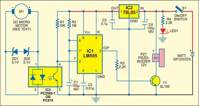
Power supply switch S1 should be kept ‘on’ when you are using this bicycle guard. When it is flipped towards ‘on’ position, the circuit gets power from the miniature 12V battery. Now LED1 lights up and resistor R4 limits the LED current. Next, the monostable built around IC1, which is CMOS version of timer LM555, is powered through a low-current, fixed-voltage regulator IC2 (78L05).

Circuit operation
Initially, when the bicycle is standing still, the monostable output at pin 3 of IC1 is low and the circuit is in idle state. In the event of a theft attempt, forward or reverse rotation of the DC motor induces a small voltage at its DC input terminals and the internal LED of 4-pin DIP AC input isolator optocoupler IC3 (PS2505-1 or PC814) glows. As a result, the internal transistor of IC3 conducts and pin 2 of IC1 is pulled low by the optocoupler and the monostable built around IC1 is triggered.
The output at pin 3 of IC1 now drives piezobuzzer-driver transistor T1 via resistor R3 and the buzzer starts sounding to alert you. In this circuit, the buzzer remains ‘on’ for around two minutes. You can change this time by changing the values of resistor R2 and capacitor C1.

Zener diodes ZD1 and ZD2 (each 5.1V) act as a protector for optocoupler IC3. The costly GP12V/27A battery is used here due to its compact size and reliability. 12V active buzzers with high-pitched tone output may be used with this circuit. These are readily available in the market.
Note
The specific optocoupler is used here deliberately, instead of a bridge rectifier, to increase the circuit’s detection sensitivity. Never replace the same with a DC optocoupler.
The article was first published in October 2005 and has recently been updated.
