


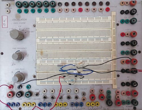
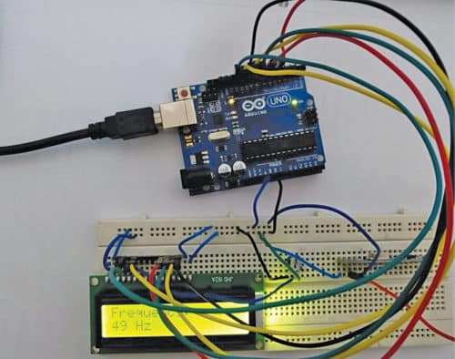
This project demonstrates an Arduino-powered wireless frequency meter that can measure the frequency of sinusoidal AC transmissions ranging from 50Hz to 3kHz. Figures 1 and 2 show prototype representations of the transmitter and receiver, respectively.
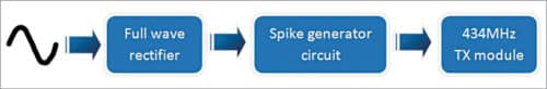
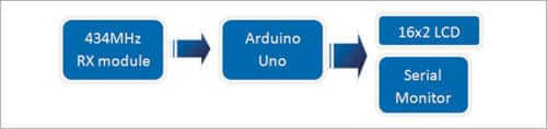
The block diagrams of the transmitter and receiver sides are shown in Figs 3 and 4, respectively.
Wireless Frequency Meter – Circuit and Working
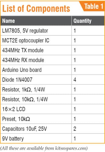
The main components used in the Wireless Frequency Meter project and their role is described below.
Arduino Uno
Arduino Uno is an AVR ATmega328P microcontroller (MCU)-based development board with six analogue input pins and fourteen digital I/O pins. The MCU has 32kB ISP flash memory, 2kB RAM and 1kB EEPROM. The board provides the capability of serial communication via UART, SPI and I2C.
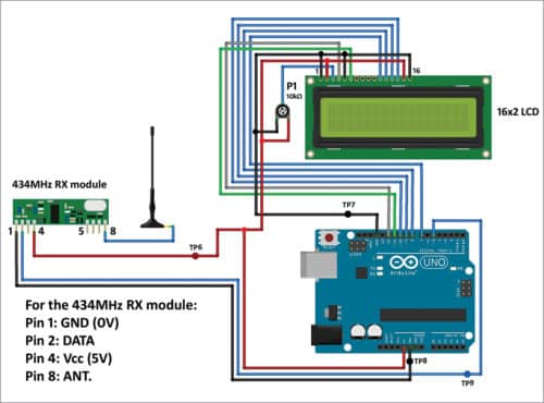
The MCU can operate at a clock frequency of 16MHz. In our project, Arduino Uno is used on the receiver side. Digital I/O pin 5 is used as input pin and is connected to DATA pin of 434MHz RX module. Digital I/O pins 7, 8, 9, 10, 11 and 12 of Arduino are used to interface with the 16×2 character LCD to display the value of the measured frequency.
Rectifier Diodes
Rectifier diodes (1N4007) are used to rectify the alternating input signal to pulsating DC on transmitter side.
MCT2E
MCT2E opto-coupler IC is used to isolate input side from the next stage and also produce signals from pulsating DC waveform on transmitter side.
LCD
The 16×2 LCD, present at the receiver end, is used to display the value of frequency. It is interfaced with Arduino Uno board in four-bit mode. LCD pins RS, EN, D4, D5, D6 and D7 are connected to digital I/O pins 12, 11, 7, 8, 9 and 10 of Arduino, respectively.
434 MHz TX-RX Modules
The 434MHz transmitter (TX) and receiver (RX) modules are used to transmit and receive radio frequency (RF) signals between two devices. Carrier frequency of the module used here is 434MHz.
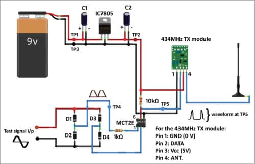
The circuit diagrams of the transmitter and receiver sides are shown in Figs 5 and 6, respectively.
Download source folder: click here
The signal whose frequency is to be measured is applied to test signal input terminals, as shown in the transmitter-side circuit diagram (Fig. 5). In this frequency meter, test signal must be an alternating one and its amplitude must not be greater than 10V peak-to-peak.
The next stage is a bridge rectifier, which converts the alternating signal to a fully-rectified pulsating DC signal. The signal is then applied to pin 1 of MCT2E opto-coupler. Pin 1 is connected to anode of the internal LED of the opto-coupler.
With the help of the opto-coupler, spikes are produced. Frequency of the signal is twice that of test signal input. The signal is applied to DATA pin of 434 MHz TX.
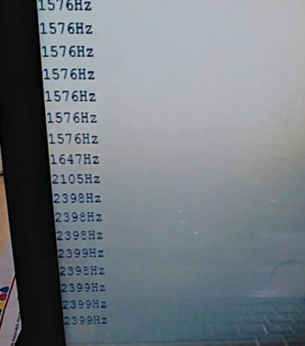
On receiver side, 434MHz RX module demodulates the received signal. DATA pin of 434MHz RX is connected to digital I/O pin 5 of Arduino Uno, which calculates frequency of the test signal and displays it on the LCD and serial monitor of Arduino IDE. Test signal frequencies 1576Hz and 2399Hz displayed on the serial monitor are shown in Fig. 7.
This project can be used for experimenting, learning, testing and troubleshooting audio equipment in the audible range between 50Hz and 3kHz.
Arduino Code for Wireless Frequency Meter
Arduino IDE 1.6.5 is used for programming Arduino Uno. Select the proper COM port and board from Tools menu in the IDE. Upload freq_meter_wl_1.ino source code to the board.
From Tools menu of Arduino IDE, open the serial monitor and select the proper baud rate (9600 is used here) to display the frequency on the serial monitor.
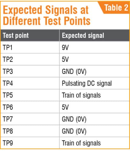
For troubleshooting, test the signals at different test points marked in the circuit diagrams. Expected voltages at different test points are listed in Table 2.
Recommended: Explore our extensive collection of Arduino projects.
Further Enhancements and Uses
- Application: This wireless frequency meter measures frequencies throughout audio ranges, making it suitable for repairing audio equipment and educational settings that require wireless frequency transfer.
- Expandability: This device can measure higher frequencies with adjustments to the frequency input range or wireless modules. Additionally, adding extra display elements or incorporating SD card storage for frequency logs could increase the project’s versatility.
Saikat Patra is passionate about electronics and microcontroller-based embedded system applications.
Shibendu Mahata is M.Tech (gold medalist) in instrumentation and electronics engineering from Jadavpur University. He is interested in designing microcontroller-based real-time embedded signal processing and process control systems
This article was first published on 28 December 2019 and recently updated in October 2024.

Hi
Can i have the program code for this project
Im also looking for the program code
You can download the Source Code from here.
How may I simulate this whole project in Proteus?
I am not getting desired output and I have connected every component as it is given above.
I Am not getting source code can anyone send me on my mail or here?…i want it urgent my email is [email protected]..
Already updated, you can download the source code now.