


 Capacitive sensors are widely used to measure various physical and chemical process parameters such as displacement, acceleration, thickness, force, pressure, stress, level and humidity. The measured value of capacitance is then calibrated in terms of the process parameter for indication and/or control.
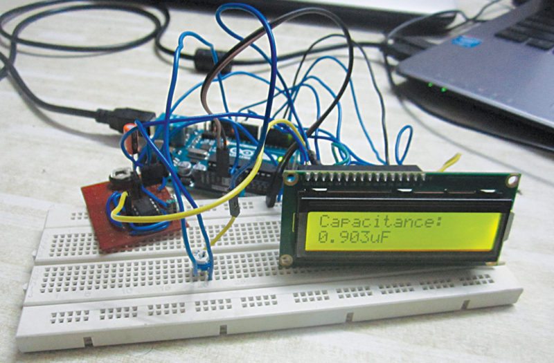
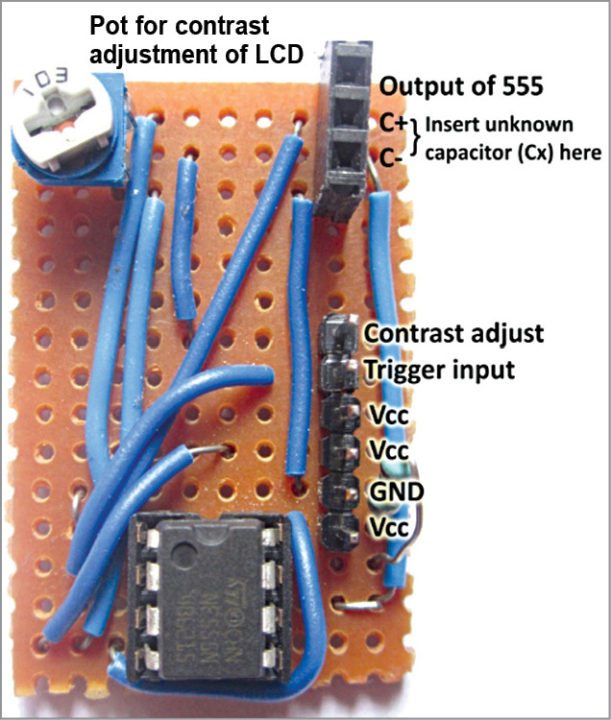
This project presents an interrupt based approach by employing an NE555 timer and Arduino Uno to measure capacitance in the range of 1µF to 1mF, and provide local indication using an LCD and data acquisition using a PC display (serial monitor of Arduino IDE). The authors’ prototype of the digital capacitance meter is shown in Fig. 1.
Two methods have been described here: first with NE555 timer configured in astable multivibrator mode and second with NE555 timer configured in monostable mode.

Capacitance Meter Circuit and Working
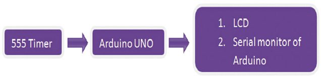
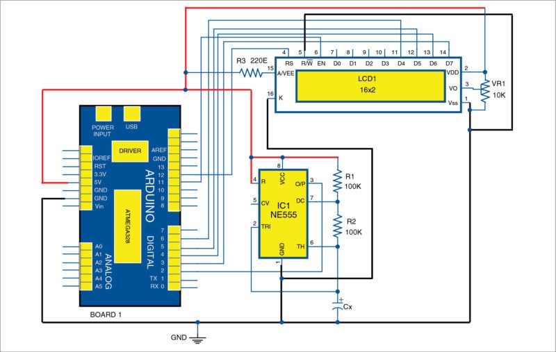
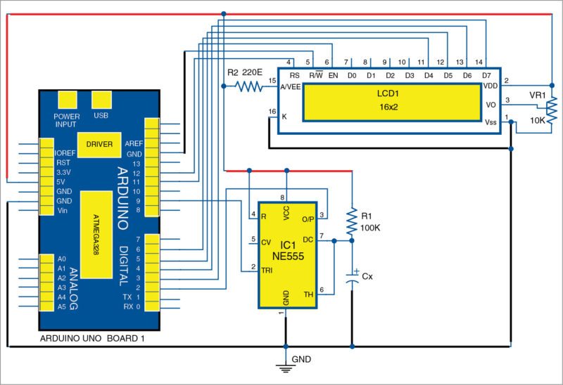
Block diagram of Arduino based digital capacitance meter is shown in Fig. 2 and its circuit diagram with NE555 timer in astable multivibrator mode is shown in Fig. 3.
Here, NE555 timer (IC1) is operated with two external resistors (R1 and R2) and an unknown capacitor (Cx), whose value is to be measured. IC1 is powered with +5V from Arduino board (Board 1); thus, eliminating the need for an external DC power supply.

IC1 generates a square-wave output of +5V amplitude at a specific frequency (depending on values of R1, R2 and Cx), which is available at its output pin 3. Output pin 3 of IC1 is connected to pin 2 of Arduino board.
Since this pin of Arduino is a hardware interrupt pin (called Interrupt 0), source code (capacitance1.ino) uploaded to Arduino uses an interrupt handler, which is executed whenever the timer output makes a low-to-high transition.
Thus, time period of the square-wave is continuously obtained by calculating the time difference between two such consecutive transitions. Time-period (T) of oscillation for the square-wave output from IC1 is given as:
T=0.693×(R1+2×R2)×Cx
Thus, value of Cx is given as:
Cx=1.443×T/(R1+2×R2)
Measured value of Cx (in µF) is then displayed on a 16×2-character LCD and PC.
NE555 timer
NE555 timer IC1 operates as an oscillator in astable multivibrator mode with free-running frequency, and duty cycle is accurately controlled by R1, R2 and Cx. Pins 4 and 8 of IC1 are connected to +5V connector of Board 1.
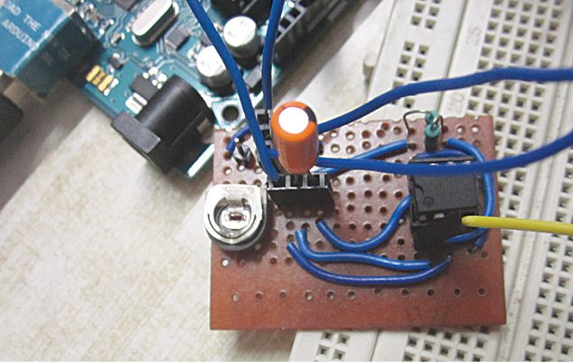
R1 and R2 of 100-kilo-ohm each are connected between pins 6 and 7, and pins 7 and 8, respectively, of IC1. IC1 shares the same ground with Arduino board. The author’s designed breakout board for the timer is shown in Fig. 4.
Arduino Uno board
Arduino Uno is an AVR ATmega328 microcontroller based development board with six analogue input pins and 14 digital I/O pins. The microcontroller has 32kB of ISP flash memory, 2kB RAM and 1kB EEPROM. The board provides serial communication via UART, SPI and I2C.
The microcontroller can operate at a clock frequency of 16MHz. In this project, digital I/O pins 3, 4, 5, 6, 11 and 12 of Arduino are connected with pins 14, 13, 12, 11, 6 and 4, respectively, of the LCD.
16×2 character LCD. Since our Arduino program (capacitance.ino) uses the LCD in 4-bit mode, only LCD data lines D3-D7 are configured for reading data from Arduino. Pins 1 and 2 of the LCD are connected to GND and 5V, respectively, from Arduino board. Read/write pin (pin 5) of the LCD is connected to GND. A 10-kilo-ohm potentiometer (VR1) is provided for adjusting the contrast of the display.
Software
The source code (capacitance1.ino) is written in Arduino programming language. Atmega328/Atmega328P is programmed using Arduino IDE software. Select the correct board from Tools→Board menu in Arduino IDE and burn the program (sketch) through the standard USB port in your computer.
Here, code written in Arduino uses LiquidCrystal.h header file provided by Arduino library for working with the LCD.
lcd.begin(16, 2) function helps configure the 16×2 character LCD.
Serial.begin(9600) function initialises the serial port with a baud rate of 9600.
attachInterrupt(0,cap,RISING) function calls interrupt handler ‘cap’ whenever a signal connected to interrupt 0 pin (pin 2) of Arduino makes a low-to-high, that is, rising-edge transition.
Serial.print(capacitance, 3) function prints the measured value of capacitance up to three decimal places using the serial port on the PC monitor.
lcd.setCursor(0, 1) function sets the LCD cursor position to print from first column of second row.
lcd.print(capacitance, 3) function prints the measured value of capacitance up to three decimal places on the LCD screen.
NE555 timer in monostable mode
In the second method (Fig. 5), NE555 timer (IC1) is operated in monostable multivibrator mode with external resistor R1 and an unknown capacitor (Cx), whose value is to be measured. IC1 is powered with +5V from Arduino board (Board 1); thus, eliminating the need for an external DC power supply.
In this mode of operation, when trigger pin of the timer is made low (0V) by sending an active low pulse from pin 9, output of the timer (from pin 3) goes high (+5V) for a certain period of time, which is determined by the values of R1 and Cx. Time period (T) for which the timer’s output remains high is given as:
T = 1.1×R1×Cx
Output of the timer is connected to pin 2 of Arduino, which is a hardware interrupt pin (called Interrupt 0). The source code (capacitance2.ino) uploaded to Arduino uses an interrupt-within-an-interrupt handler, that is, a two-level nested interrupt sub-routine (ISR).
The first interrupt-handler gets executed whenever the timer output makes low-to-high transition, and the second ISR is called from within the first when timer output makes high-to-low transition. Thus, time for which the output of the timer remains high is obtained by calculating the time difference between two such consecutive interrupts, which is equal to T.
Thus, value of Cx is given as:
Cx = T/(1.1×R1)
Measured value of Cx (in µF) is then displayed on a 16×2-character LCD and serial monitor of Arduino IDE.
NE555 timer
NE555 timer IC1 operates in monostable multivibrator mode, where time for the output goes high, after applying high-low-high pulse from pin 9 of Arduino, which is controlled by R1 and Cx connected externally to the IC.
Output of timer pin 3 is connected to interrupt pin (pin 2) of Arduino. Pins 4 and 8 of the IC1 are connected to +5V connector of Board 1. R1 of 100k is connected between pins 8 and 7. IC1 shares the same ground with Arduino board. The authors’ designed breakout board for the timer is shown in Fig. 6.
Software
The code (capacitance2.ino) written in Arduino programming language uses LiquidCrystal.h header file provided by Arduino library for working with the LCD.
attachInterrupt(0,analyze1,RISING) function calls the interrupt handler named analyze1 whenever output of IC1 connected to interrupt 0 pin (pin 2) of Arduino makes low-to-high, that is, rising-edge transition.
attachInterrupt(0,analyze2,FALLING) function calls the interrupt handler named analyze2 whenever output of IC1 connected to pin 2 of Arduino makes high-to-low, that is, falling-edge transition.
The high-low-high trigger pulse applied to pin 2 of IC1 is generated by pin 9 of Arduino using the following code within void loop() function. Refer source code for the same.
void loop ( ){
digitalWrite(9, HIGH);
delay(10);
digitalWrite(9, LOW);
delay(1);
digitalWrite(9, HIGH);
while (1);
}
Note. To test a new capacitor (Cx), connect the capacitor and press Reset on Arduino Uno board.

Can we measure unpolarised capacitor values using this method???
Yes, you can measure the values of polarised and unpolarised capacitors.
what is the measuring range ….. can i measure any capacitor ??
Please read the article. It is clearly mentioned that this circuit can measure capacitance in the range of 1 micro Farad to 1 milli Farad
i want to do a school project on Arduino based digital capacitance meter with NE555 timer in astable mode, but didn’t understand it
I have built the circuit, downloaded the code for capacitance 1 and uploaded it to Arduino and run it The lcd displays Capacitance: 0.000uF even with a 10uf capacitor used as Cx. I don’t know how to solve it . it may be the code. I have double checked the circuit Arduino to LCD display and the 555 but nothing wrong. Perhaps you can help?