 Segbot, Segway and inverted pendulum—two-wheel self-balancing robots are known by many names. Here we build a two-wheel self-balancing robot (segway) using an MPU-6050 chip. The inertia-measuring MPU-6050 chip has six motion sensors—three gyros and three accelerometers—all integrated into one breakout board.
Here, we only need angular position or gyro of the wheel’s axis. Gyro readings drift over time, requiring recalibration quite often. Therefore, to get correct angular position, gyro readings are corrected with the help of a neighbouring accelerometer. Once the angular position is achieved, traction motors push the cart towards the direction of falling. The greater the angle of shift, the greater the speed with which the traction motor pushes the cart. As the angle of shift wrt vertical position reduces to zero, the speed reduces. Thus, the top of the cart moves like a pendulum, maintaining the balance. The author’s prototype is shown in Fig. 1.
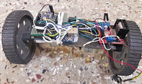
Circuit and working of Self-Balancing Robot
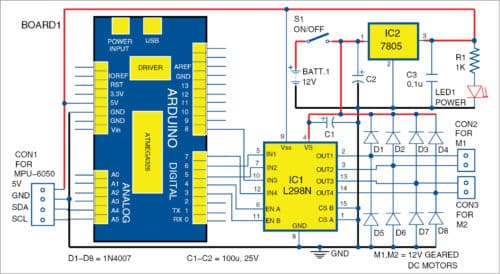
Circuit of the two-wheel self-balancing robot is shown in Fig. 2. It is built around an Arduino Uno (Board1), dual full-bridge driver L298N (IC1), 5V regulator 7805 (IC2), MPU-6050, two DC motors and a few other components.
Motors
We have used two 12V, 300rpm, geared and brushed DC motors and two 100mm wheels. Initially, brushed motors work fine but over time, with use, these tend to develop instability and inability to balance the robot. The best option is to use brushless DC motors, which have great torque-to-rpm characteristics. However, these have a direction reversal problem.
Another option is to use stepper motors, but their lesser rpm hinders balance. However, there are reports of people successfully using stepper motors with Segway bots.
L298N
Motor driver L298N is available either in a multiwatt15 or powerSO20 package. It is a high-current, dual full-bridge driver for inductive loads including relays, solenoids, DC and stepping motors. Two enable inputs (pins 6 and 11) are provided to enable or disable the device independently of the input signals. One bridge is driven by IN1, IN2 and EN A, and the other by IN3, IN4 and EN B pins of IC1.
Software
We have used Jeff Rowberg I2Cdev libraries for MPU-6050. Arduino Uno board is programmed with the main program two_wheel.ino. The main software has three variables: kp, kd and ki. Default values work well but can be changed to provide more stability to the robot. To change the values, you need mpu_calibration.ino code as explained in Calibration section.
Compilation. There was a minor glitch while compiling the sketch on Arduino IDE 1.1 as MPU-6050 libraries were not getting installed. So we installed Arduino 1.5.7 and imported libraries from the main menu by indicating the correct location of libraries with SketchImport LibraryAdd Library options. After all the libraries get added to Arduino IDE, compile the sketch and upload it to the board.
Download Source Folder
Construction and testing
An actual-size PCB layout of the two-wheel self-balancing robot is shown in Fig. 3 and its components layout in Fig. 4. Use a suitable metallic chassis for the robot. Mount the Arduino board on the chassis of the robot. Then place the PCB on top of the Arduino board.
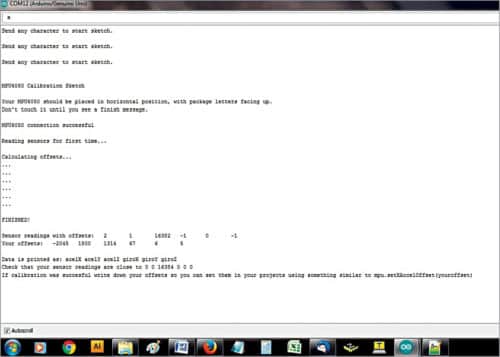
First, burn the mpu_calibration.ino code into Arduino, attach the MPU-6050 and upload the sketch to the Arduino board. Then open the serial monitor and select baud rate as 115200. After initialisation of the DMP (digital motion processing)—on-board processor of the MPU-6050—press ‘a’ followed by Enter key. You will get a screen as shown in Fig. 5. Note that your offset values will be different.
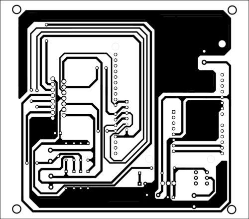
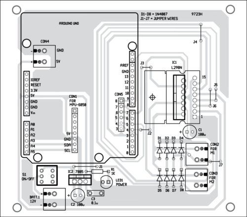
Download PCB and component layout PDFs: click here
Note down the offset values. Then open the main two_wheel.ino code and enter the test offset values. Compile and upload the main code to the Arduino. Connect the motors, battery and switch on the circuit. Place MPU-6050 along the wheel axis of motors to ensure minimal error of calculation.
First, run the robot with a lightweight 12V battery. The best way is to first use a 12V AC/DC adaptor for the power supply. Once you are sure that the robot is working well, put the battery inside the chassis.
Calibration
As mentioned earlier, gyro readings drift over time. To counter the problem, first you need to find out the gyro offset for each different set of gyros.
For MPU-6050 type gyros, here’s the simplest way: First load mpu_calibration.ino to your Arduino, attach MPU-6050 on a horizontal surface, stabilise it for some time, switch off all the ceiling and table fans during calibration, and get offset readings on the serial monitor as mentioned earlier. Insert these values in the offset fields of the main program. Compile and upload it to your Arduino processor and then try to run the robot again. If the robot is not working well, repeat the calibration process until you get a satisfactory result.
Video Demo


