 This simple AT89C2051 based electronic dice circuit demonstrates the capability of an AT89C2051 microcontroller chip to function as a random number generator based on the flying counter principle. The program in the chip constantly updates the counter variable, which, on being interrupted by an external trigger, latches the counter value and displays a random number through its output ports. This method is similar to the one used in PCs or calculators for generating random numbers at any instance.
AT89C2051 based electronic dice circuit

The use of IC AT89C2051 (IC1) module in the design is quite simple. It operates off 3-5.5V DC supply and uses an 18MHz crystal to generate the clock (refer Fig. 2). Switch S1 connected at pin 1 is used as a reset switch. Interrupt occurs at pin 6 of IC1 on logic 0. Switch S2 connected to pin 6 (INT0) of IC1 is used to trigger an external interrupt to make pin 6 low. It is used as input to generate the random number. The random number is indicated by glowing of the LEDs (LED1 through LED7) connected to port pins P1.2-P1.7 and P3.7.
TL0 and TH0 act as free-wheeling counters in auto-increment mode and constantly count up from the initial value. When the interrupt occurs, the value from the counter is latched and glowing LEDs indicate the random number generated by the microcontroller chip. Assembly language is used for programming the chip. The Assembly code listing is self-explanatory.
Circuit operation
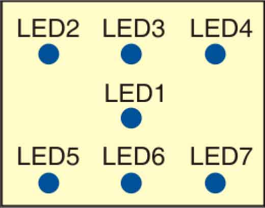
The application of this dice is similar to the one used in a game of dice. The random numbers generated are not displayed numerically, but represented by the number of glowing LEDs. The LEDs are the dot representation on the face of a dice. Suggested LED arrangement for the electronic dice display is shown in Fig. 1.

EFY note
The source code was included in the EFY-CD and also available on www.efymag.com website
The article was first published in June 2010 and has recently been updated.


