


 This circuit can be used to control up to four electrical devices through a cellphone or computer. The main advantage is that you can login from anywhere to control the device(s). If you try to login using invalid credentials 10 times, the system gets locked for the next three minutes.
Both NodeMCU v0.9 and NodeMCU v1.0 boards are based on ESP8266 Wi-Fi microchip, so the same program can be used for both. NodeMCU v0.9 consists of ESP12 chip and NodeMCU v1.0 consists of ESP12E/12F chip.
ESP8266 can be used in two different modes: station (STA) and soft access point (SAP). In STA mode, ESP8266 can connect to the Internet via another access point.
In SAP mode, ESP8266 broadcasts its own access point. Any device with Wi-Fi capability can be connected to it and used to control the device(s).

Circuit and working
The circuit diagram of the device control with authentication is shown in Fig. 1.

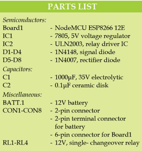
Main controller of the circuit is NodeMCU. It gets commands from the other devices connected to it through Wi-Fi and then it changes the output pins to either on or off state according to the given command. Note that, one of the coil terminals of all the relays (RL1 through RL4) is connected to the positive rail of the 12V battery.

Here, pins D5 through D8 of NodeMCU are used as outputs. If device1 is switched on using Wi-Fi, then pin D5 goes high, which makes pin 1 of ULN2003 high through diode D1. As a result, output pin 16 of IC2 goes low. So, RL1 gets activated and the first load gets switched on.
Similarly, if device1 is switched off using Wi-Fi, then output pin D5 goes low, pin 1 of ULN2003 goes low, and as a result pin 16 goes high. So, RL1 gets deactivated and the first load gets switched off. The same is applicable to the remaining output pins of NodeMCU, and electrical devices/loads are turned on or off, accordingly.
Software and its installation
1. Download and install the latest Arduino IDE from Arduino website.
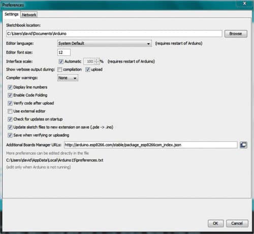
2. Open Arduino IDE and go to File→Preferences under Settings, and paste the url http://arduino.esp8266.com/stable/package_esp8266com_index.json on Additional Board Manager URLs, as shown in Fig. 2.
3. Open Arduino IDE and go to Tools→Board→Boards Manager (Fig. 3).
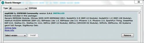
4. Type ESP8266 in Search box, and install the latest version of ESP8266 by ESP8266 community.
5. After installation is complete, go to Tools→Board. Scroll down and select the correct board you are using (NodeMCU 0.9, NodeMCU 1.0, etc).
6. Go to Tools→Erase Flash and select Sketch+ Wi-Fi settings.
7. Connect the board to the computer, go to Tools→Port and select the correct COM port.
Arduino program
The program (device_web.ino) is written in Arduino programming language and compiled using Arduino IDE. Open the program into Arduino IDE and make necessary changes to the program (as explained below). Save and then upload the program to NodeMCU.
The following lines can be modified in Arduino program/sketch according to requirements:
#define stationMode false // if false, ESP8266 is in SAP mode or else it is in STA mode.
(STA mode is tested at EFY Lab.)
const char* ssid = “*****” // string is used to store the access point name to ESP8266 module. It will connect to SAP, which ESP8266 will broadcast.
const char* password = “********” // string is used to store the password of the access point or SAP.
String username = “admin” // string is used to store the username of the login page.
String loginPassword = “admin” // string is used to store the password of the login page.
String headingMessage = “ “ // string is used to set the headlines of the webpage.
int noOfTry = 10 // 10 is the number of false entries allowed.
int lockDownTime = 180000 // 180000 is lockdown time (in milliseconds).
int cookieExpireTime = 60000 // 60000 is cookie expiration time (in milliseconds).
int refreshTime = 10 // 10 is refresh time (in seconds) for status check webpage.
Some functions used in this program are explained below.
statuscheck() function is called when a URL is requested from the browser, for example, IPADDRESS/status URL.
genrateCookie() is used to generate a 32-bit cookie by taking characters randomly from string ranchars.
if_authenticated() is used to check whether the cookie is valid or not.
StatusCheck() is used to check the status of output pins.
background-color: #ff1d00 value can be changed to change the colour of buttons under void webpage().
Construction and testing
An actual-size PCB layout of the device control is shown in Fig. 4 and its components layout in Fig. 5. Power up NodeMCU board. If NodeMCU is configured as SAP mode, then connect it to the access point broadcast by NodeMCU. Open the Web browser on a cellphone or computer. Type 192.168.4.1 (default IP) in the address bar and press Enter.

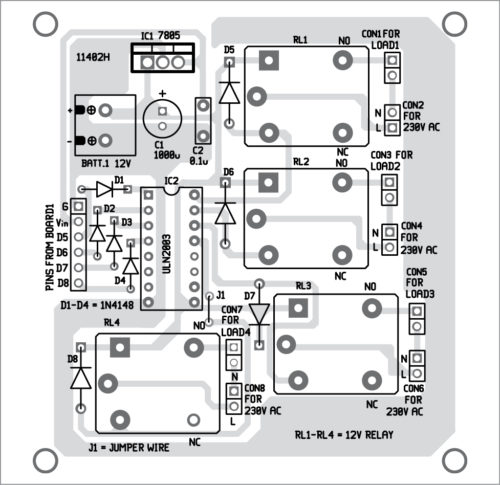
Download PCB and Component Layout PDFs: click here
If NodeMCU is configured as STA mode, use the IP address of NodeMCU. To find out the IP address of NodeMCU, you may refer to https://tttapa.github.io/ESP8266/Chap07%20-%20Wi-Fi%20Connections.html
Open the Web browser on a cellphone or computer. Type the IP address of NodeMCU in the address bar and press Enter.
The login webpage will look as shown in Fig. 6. IP address of NodeMCU may be different in your case.
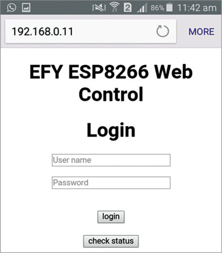
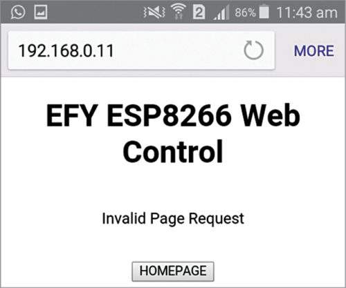
Note that, if there is no activity for some time on the login page, it will automatically log out after the session expires. If an invalid page is requested, it will give an error message, as shown in Fig. 7.
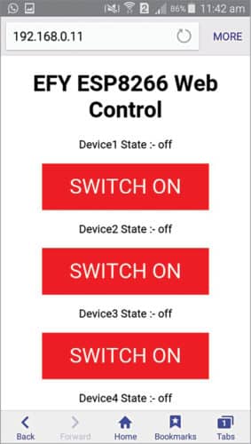
Click on Check Status shown in Fig. 6 to see the status of all four devices. The webpage will refresh as per the instructions given in the program code. To login, fill in the user name as admin and password as admin, and click on Login. (You can customise the user name and password in the program code and use these details during login.) Now, you will be able to switch on or switch off the device. Fig. 8 shows the control panel with device status.
 In case of invalid login credentials, the program will display an error message along with the number of attempts. If invalid login attempts equal 10, or value of noOfTry defined in the code, the program will lock down for some time as defined by lockDownTime in the code. After preset lock-down time, the program will automatically unlock and you can try again with valid credentials.
Download source folder: click here
David Hembram is an electronics hobbyist. His interests include circuit designing, PCB designing, programming embedded systems, Arduino, PIC and Raspberry Pi.

This project is awesome. I’ve been search the web for this kind of sketch for months… now my dream come true. Thank you for sharing this masterpiece!
You are most welcome.