


 Telephone conversation can be made disturbance-free using this simple circuit. As soon as you lift the telephone handset to converse, the TV, music system or any other appliance that may be causing disturbance gets switched off. It turns on when you place the handset back on the cradle.
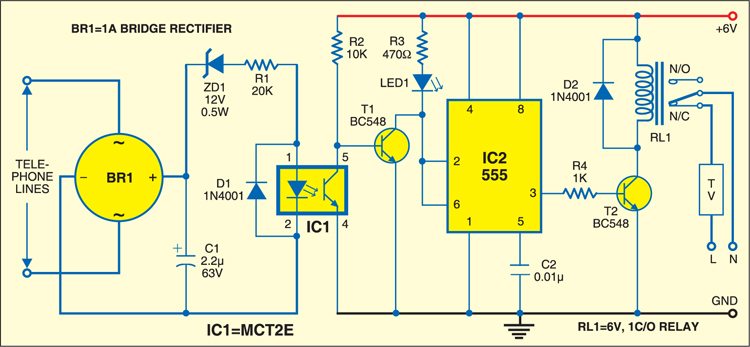
This is achieved using a polarity-guard circuit comprising bridge rectifier BR1, optocoupler MCT2E (IC1) and timer 555 (IC2) along with the associated circuitry as shown in Fig. 1. Normally, the voltage across telephone lines is about 48V. However, when you lift the telephone receiver off the cradle, it drops to about 9V.
When the telephone receiver is on the cradle, the zener diode conducts and current passes through the internal LED of optocoupler IC1. As a result, its internal transistor conducts and transistor T1 stops conducting. This makes pins 2 and 6 of IC2 high and thus its output at pin 3 becomes low. This low output of IC2 makes relay-driver transistor T2 non-conducting and relay RL1 remains de-energised. As a result, the TV or music system remains on through the normally-closed (N/C) contacts of the relay.

On the other hand, when the handset is lifted off the cradle, the zener diode stops conducting and no current passes through the internal LED of optocoupler IC1. As a result, its internal transistor stops conducting and transistor T1 conducts. This makes pins 2 and 6 of IC2 low and thus its output at pin 3 become shigh. This high output of IC2 makes relay-driver transistor T2 conducting. Thus relay RL1 energises to disconnect power supply to the TV or music system. At the same time, LED1 glows to indicate that conversation is going on.
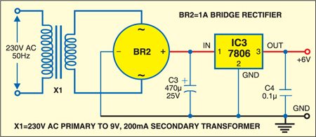
The circuit works off a regulated 6V power supply. Transformer X1 steps down 230V AC mains to give a secondary output of 9V at 200 mA. The transformer output is rectified by full-wave bridge rectifier BR2, filtered by capacitor C3 and regulated by IC3 (7806). The regulated 6V output of IC3 is used to power the circuit as shown in Fig. 2. Capacitor C4 bypasses any ripple in the regulated output. Instead of regulated power supply, you can also use a 6V battery.

Assemble the circuit on a general-purpose PCB along with the power supply and house in a suitable cabinet. Install the circuit in parallel to the telephone.
