


 DC motors are widely used in different machines, mechanisms and motion controls in manufacturing and processing industries. In these machines, it is often required to control speed, direction and the number of rotations of the motor. Some applications require only motor speed control, some only rotation control and some only direction control. Many applications require control of two or all three parameters. Some examples are:
1. To release the thread (or wire) of desired length from a bobbin, it is required to rotate the bobbin for a specific number of rotations. Also, there is a need for controlling the speed at which the thread is released.
2. In a coil-winding machine, it is required to make a specific number of coil turns. This is done by rotating the motor for a specific number of rotations. Also, it is required to vary the motor speed to speed up/down the operation.

3. In a conveyor belt application, to move the object to an exact distance, it is required to rotate the motor for a desired number of rotations.
4. In an automatic storage and retrieval system, it is required to rotate the motor clockwise and anticlockwise to move up and down, or left and right. Also, the motor has to be rotated for a desired number of rotations to reach a specific position.

5. In a robotic arm, to pick and place an item, it is required to rotate the motor clockwise and anticlockwise for a desired number of rotations. Speed control is also required for slow or fast operation, accordingly.
There are many more examples and applications where it is required to control speed, direction and rotations of a DC motor.
Auto reversible DC motor control project
This project is an auto-reversible DC motor that automatically reverses when it completes the desired number of rotations. It is an example of a closed-loop control system that utilizes feedback loop. It counts the actual number of motor rotations and gives feedback to the system. The system compares a set of rotations with actual motor rotations, and when these match, it reverses the motor.
It can repeat this operation in a continuous loop if repeat mode is selected. It also controls the speed of motor from 10 to 100 per cent.
The motor starts with 10 per cent speed and gradually attains the selected speed as it completes three to six rotations. Also, when the motor reaches the last six to ten revolutions, the speed gradually decreases, and for the last two rotations it becomes 10 per cent. This speed control is used to precisely stop the motor at the desired number of rotations point and for smooth operation.
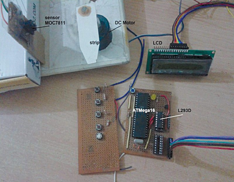
The project utilises an ATmega16 microcontroller to control the DC motor, an LCD display to show various parameters and an opto-interrupter sensor to count motor rotations and provide feedback. The author’s prototype, including motor-sensor arrangement, is shown below.
Circuit and working
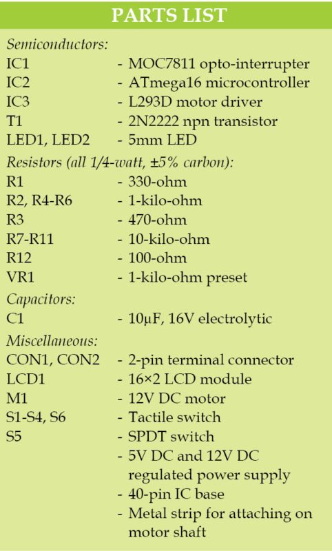
Circuit diagram of the auto reversible DC motor control is shown below. It is built around opto-interrupter module MOC7811(IC1), ATmega16 microcontroller (IC2), 16×2 LCD (LCD1), motor driver L293D (IC3), 12V DC motor (M1) and a few other components.
Four push-to-on button/tactile switches (S1 through S4) are connected to port C pins PC0, PC1, PC6 and PC7 of IC2, so that when a button is pressed, it gives a high logic (1) input to the corresponding pin. These switches are used for various settings to control the motor, including up, down, enter and rotation.
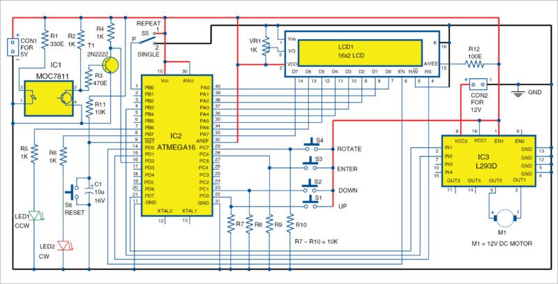
LCD1 is connected to port A and port D of IC2. Its data pins are connected to port A, and the control pins EN and RS are connected to PD0 and PD1, respectively. LCD1 displays the number of rotations and speed of the DC motor.
Port D pin PD7 and port B pin PB3 of IC2 drive the DC motor through motor driver chip L293D. These pins are connected to input pins 2 and 7 of the L293D, and output pins 3 and 6 of the L293D are connected to the motor (M1) terminals.
PB3 and PD7 are PWM output pins. PWM output on these pins will vary the speed of motor. Also, when PB3 generates PWM, PD7 is off and the motor rotates in forward (clockwise) direction, and when PD7 generates PWM, PB3 is off and motor rotates in reverse (anticlockwise) direction.
Opto-interrupter sensor MOC7811 consists of an IR LED and a phototransistor. The internal IR LED is forward-biased to keep it continuously on. A current-limiting resistor (R1) of 330-ohm is used to limit the current flowing through it. Output of the phototransistor is given as input to the base of transistor T1 that is connected in switch mode. Final output of the sensor circuit is taken from collector of T1. This output is given to external interrupt 0 input pin PD2 of ATmega16.
SPDT switch S5 is connected to port B pin PB0, so that when it is connected to +5V it gives logic 1 input, and when connected to ground it gives logic 0 input to pin PB0. S6 is used as the reset switch for IC2.
LED1 and LED2 are connected to pins PB6 and PB7 of IC2 for anticlockwise and clockwise indications, respectively.
Circuit operation
The motor is initially in stop position. When power is connected to the circuit, “Set rotations” message is displayed on LCD1. Here, you need to enter the required number of motor rotations by pressing S1 or S2. These two switches work as up and down arrow keys for the number of rotations and speed, respectively.
S1 is used to increase the number of rotations by five, and S2 is used to decrease the number of rotations by five. The minimum number of rotations is ten.
Once the desired number of rotations is selected, press Enter (S3). The LCD display will show “Rotations set to xx” message. After two seconds, you will be prompted to enter the required speed, when the LCD displays “Set motor speed” message.
You can set the speed from 10 to 100 per cent in steps of 10 by pressing up or down arrow keys. Once the desired speed is set, press Enter. The display now shows “Speed is set to xx%” message.
Now, you will be prompted to start motor M1 through “Press rotate” message on LCD1. When you press the rotate button (S4), microcontroller IC2 starts applying PWM on PD7, as per the selected speed, and the motor starts rotating anticlockwise.
LED1 turns on to indicate that the motor is rotating in anticlockwise direction. PWM width is increased to the desired speed in two or three steps, so that the motor speed increases step by step.
As the motor rotates one revolution, a light thin metal strip attached to the shaft of the motor passes through the gap of the opto-interrupter sensor module. This interrupts IR light falling on the photo-transistor for a fraction of a second. The photo-transistor gives a very short-duration positive pulse, which is inverted by transistor T1, and it gives a short-duration negative pulse to pin PD2 of IC2. This negative pulse is registered as one count by IC2. In this way, IC2 counts the number of interrupts as the number of rotations of the motor and displays it on LCD1.
As the motor reaches the last six to ten rotations, PWM width is reduced to decrease the speed. For the last two to four rotations of the motor, its speed is reduced to 10 per cent to further slow down the motor.
As the motor completes the rotations in anticlockwise direction, PWM is generated from PB3 pin. The motor starts rotating in clockwise direction. LED2 turns on. Again, motor speed is increased in steps to full speed and then decreased in steps to the minimum as it completes the desired number of rotations.
At this time, if S5 is at position 1 (repeat) and input is high at PB3 pin, the motor will continue to rotate in clockwise and anticlockwise directions at selected speeds. But if S5 is at position 2 (single) and input is low, the motor will stop after one rotation. After two seconds, you will be prompted to enter the desired number of rotations for the next operation, and the cycle will continue.
Software
ATmega16 is the main building block of this project because it performs the following tasks:
1. Takes user input from pushbutton switches to set speed, rotations, run motor and so on.
2. Rotates the motor at the desired speed using PWM technique.
3. Displays motor speed, rotations and various messages on the LCD.
4. Counts actual motor rotations.
5. Automatically reverses the motor when it completes the desired number of rotations.
6. Rotates the motor clockwise or anticlockwise in repeat mode.
To implement all the above functionalities, the software program is loaded into the internal ROM (flash) of the microcontroller. The program (DCMotor_speed.c) is written in C language and is compiled using AVR Simulator 2 available with AVR Studio IDE software. The hex code generated is used to burn into ATmega16 using a suitable programmer. (ProgISP programmer was used at EFY Lab for programming the hex code.)
Download source code
Construction and testing
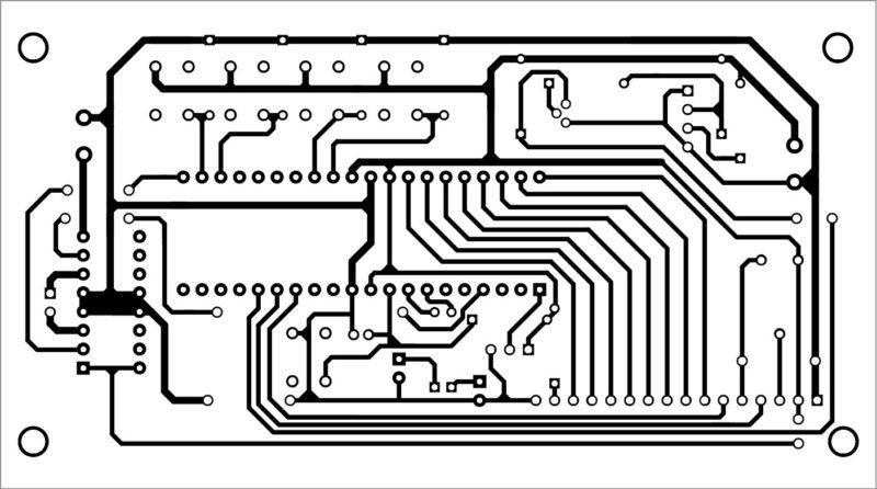
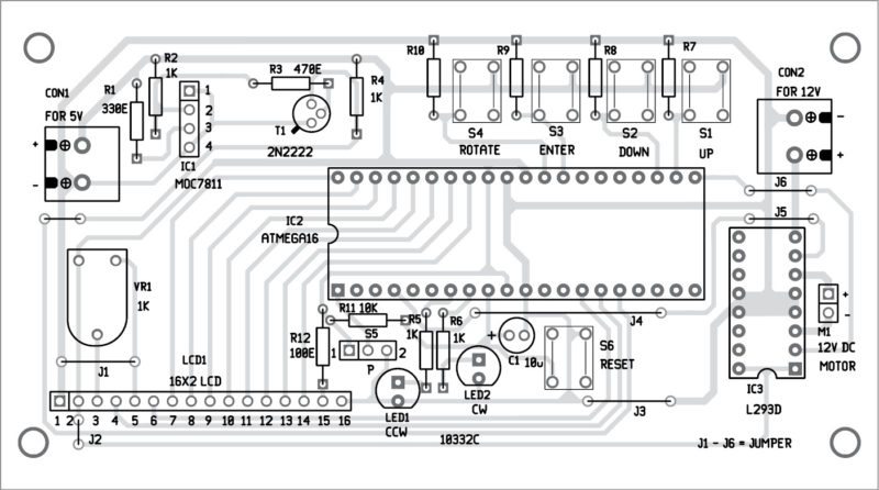
An actual-size, single-side PCB layout for the auto-reversible DC motor control and its components layout is shown in below. After assembling the circuit, enclose it in a suitable box.
 Download PCB and component layout PDFs: click here
 Download PCB and component layout PDFs:
 Fix CON1 at the back side of the cabinet and S1 through S5 at the top side of the cabinet. Fix S6 on the front side of the cabinet for resetting the circuit. Attach a light thin metal strip to the shaft of motor in such a way that when shaft rotates the metal strip should pass through the slot (cut) of the MOC7811.
After assembling the circuit on the PCB, crosscheck for any wrong connections. Burn the program (DCMotor_speed.hex) into the microcontroller using a suitable programmer.
It is recommended to use a 40-pin IC base for ATmega16. Use a 5V DC power supply for the circuit and a 12V DC power supply for the DC motor.
More interesting projects available here.

Interesting project, please provide configuration (fuse bits) settings for ATMEGA16
Please upload the source code
The source code is present on the second page.
Is this come under mini project or major project
project is tested or not…
This circuit is fully tested by EFY Team.
How should the fuse bits be, can you help me bro? I made the circuit but I can’t program because there is no fuse settings
bro the source code is not downloading and how should the insurance settings be, can you help me please
Hi, kindly refresh the page again
hi bro how should the insurance settings be please help
bro, can you please tell me how should the fuse setting be?