


 In areas like staircase or porch of your home, lighting is required only for a short period of time at night. We often forget to switch off these lights, which results in considerable wastage of electricity. Here is a simple staircase light circuit that switches the lights off automatically after a predetermined time. The circuit consumes no power when inactive.
Circuit and working
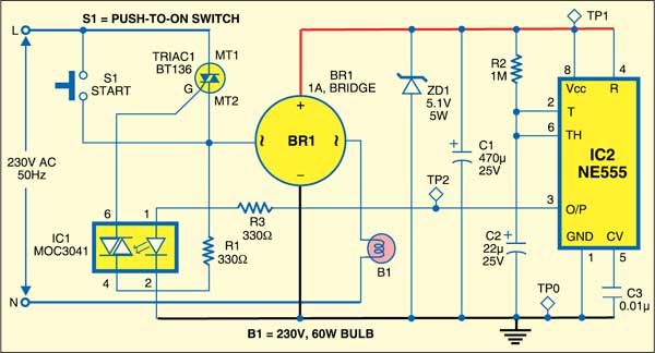
Fig. 1 shows the circuit of staircase light controller. It consists of opto-isolator MOC3041 (IC1), popular timer NE555 (IC2), triac BT136 (TRIAC1) and a few discrete components. Timer IC2 is configured in monostable mode. Momentarily pushing switch S1 triggers the timer (IC2), which keeps the triac conducting and the light bulb (B1) ‘on’ until the timer times out.

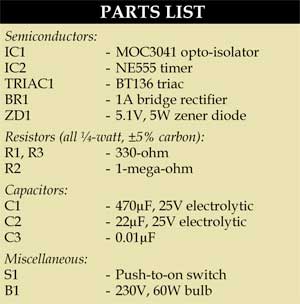
Producing a small DC voltage from AC mains to run an electronic control requires a step-down transformer or a voltage-dropping capacitor circuit. Here a tricky and easy solution is adopted. Bulb B1 gets power via the diode of bridge rectifier BR1 and zener diode ZD1. The voltage drop across zener diode ZD1 is filtered by capacitor C1. This voltage is sufficient to run the rest of the circuitry.

Working of the circuit is simple. Press switch S1 momentarily to turn bulb B1 ‘on.’ The bulb remains ‘on’ for around 20 seconds and then turns off automatically. This duration is long enough for you to find your way up or down the staircase in the dark. It can, however, be varied by changing the values of timing components R2 and C2.
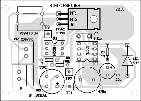
Construction and testing
An actual-size, single-side PCB for the staircase light controller is shown in Fig. 2 and its component layout in Fig. 3. Assemble the circuit on a PCB to minimise time and assembly errors. Carefully assemble the components and double-check for any overlooked error.
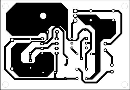
Download PCB and component layout PDFs: click here
Switch S1 should have current rating corresponding to the load. Multiple switches can be installed in parallel to switch S1 to turn on the bulb from different places, say, from top and bottom of the stairs. The circuit runs directly from mains power. So take utmost care while assembling.
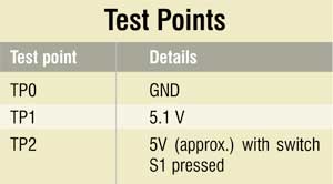
To test the circuit for proper functioning, check test points TP1 and TP2. These should be at around 5V once switch S1 is pressed.
For reading more exciting DIY projects: click here
The author is managing director of Quantum Dots Technology Pvt Ltd, Chennai, and a regular contributor to EFY

If I have more loads .say 1000watt can this circuit work,
If not please tell me what do
Thanks.
i need circuit for twenty steps staircase automatic ON step by step & off after few seconds