


 This Automatic Fan Controller circuit is based on a thermistor and an operational amplifier (op-amp) that drives a MOSFET to switch a cooling fan on and off in an active heatsink system. The design also includes an overload protection mechanism.
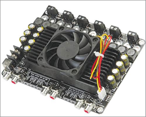
An active heatsink is normally included in electronic products such as power supplies and power amplifiers. It has a fan attached to it to actively pull heat away from it and the chip underneath. The automatic fan controller constantly monitors heatsink temperature and switches on the fan whenever the temperature rises above a pre-determined level. A typical active heatsink used in a class D power amplifier is shown in Fig. 1.
You may think that a fan controller is not required and that the fan should always be on. While that may be true to some extent, in order to reduce the irritating fan noise and prevent undesirable power consumption when power dissipation in the system is normal, the controller accomplishes the goal quite satisfactorily.

Circuit and working
The circuit diagram of the automatic fan controller for an active heatsink is shown in Fig. 2.

It is built around op-amp LM358 (IC1), two MOSFETs BS170 (T1 and T2), a small 12V cooling fan and a few other components.
As you can see from the circuit diagram, LM358 (IC1) has two op-amps. The first has pins 2 and 3, and its output is pin 1, The second op-amp has pins 5 and 6, and its output is pin 7.
The first op-amp forms a simple comparator between the voltage set by 10k NTC thermistor TH1 and 15-kilo-ohm resistor R1. The fan on threshold level (fan_set) is determined by potentiometer VR1, and hysteresis is controlled by positive-feedback resistor R2.
The thermistor is placed on the heatsink of the chip to be protected, as shown in Fig. 3.
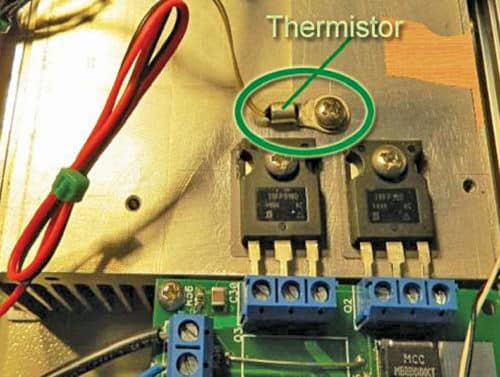
Resistance of the thermistor decreases as temperature rises.
When temperature exceeds the set threshold level, output of the first op-amp goes high. This turns on BS170 (T1) to start the connected 12V (<350mA) cooling fan.
While a thermally-controlled heatsink fan is generally a good design, a thermal overload protection for the main system is also required. For example, in a power supply unit (Fig. 3), when the system is not handling too much power, the heatsink remains cool and so the fan stays off. The fan should only be on when required. It is a trade-off between optimal cooling and noise.
Temperature in electronic devices rises due to environmental factors as well as the heat generated by the components themselves. When temperature in the main system unit exceeds the threshold level, the thermal overload protection option in the given design can shut down the main system unit.
Output of the second op-amp is used for thermal overload protection of the main system unit. This op-amp is also a voltage comparator with hysteresis, and is used to turn on another BS170 (T2) in open-drain (active-low) configuration to shutdown the main system unit (or microcontroller) when temperature exceeds a set threshold level.
The temperature threshold level (overload_set) for overload protection is controlled by VR2. It should obviously be higher than fan_set threshold level.
LED1 glows when thermal overload protection is activated. In normal state, T2 is off and very little current flows through it. Hence, this does not affect normal operation of the main system unit.
Unlike the common overcurrent fuses that open up when current exceeds the safe value, thermal protection offered here is configured to operate when surrounding temperature exceeds normal level. Thermal protection ensures that delicate electronic components are not destroyed by over-temperature conditions.
Construction and testing
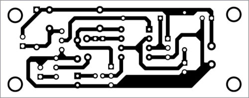
An actual-size PCB layout for the automatic fan controller for an active heatsink is shown in Fig. 4 and its component layout in Fig. 5.

Download PCB and Component Layout PDFs: Click here
Assemble the circuit on the PCB and connect 12V DC across connector CON1. Connect the cooling fan to CON2 and terminals of the power switch of the main system unit to CON3.
T.K. Hareendran is founder and promoter of TechNode Protolabz
Is there any replacement for T1 & T2 BS170 i can use for this circuit please?