


Many central air-conditioning systems (ACs) have the option for cooling and heating both. These have a fan for blowing hot or cold air drawn from a central unit, often with no automatic speed control for the fan. The speed of the AC fan has to be manually controlled to maintain a comfortable temperature throughout the room.
Manually adjusting the AC temperature is not very convenient. So we present here an automatic control system for the AC fan which could also help control the room temperature to some extent. It allows the air-conditioning system to automatically blow warm air in winters and cool air in summers without requiring manual intervention.
Circuit description
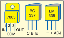
Fig. 1 shows the circuit of the automatic fan controller for the AC. It comprises regulator IC 7805 (IC1), bar-graph driver IC LM3914 (IC2), comparator IC LM339 (IC3), temperature sensor IC LM335 (IC4) and some discrete components. Pin configurations of 7805, BC337 and LM335 are shown in Fig. 2.

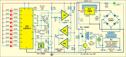
Power for the circuit is derived from mains supply. The 230V, 50Hz AC mains is stepped down by transformer X1 to deliver a secondary output of 12V, 500 mA. The transformer output is rectified by a full-wave rectifier comprising diodes D1 through D4, filtered by capacitor C6 and regulated by IC 7805. Capacitor C7 bypasses ripples in the regulated supply.
IC LM3914 is configured for bar-graph mode by connecting its pin 9 to 5V supply. It functions both as the temperature and set-point indicator, depending on whether switch S1 is in RUN or SET position, respectively. A highly stable internal reference voltage is generated at pin 7 using resistor combination R1-R2 and presets VR1 and VR2. This voltage is directly fed to the upper end of the internal voltage divider chain at pin 6. Pin 4, the lower end of the internal voltage divider chain, is connected to the wiper of preset VR1. The voltage difference between pins 4 and 6 determines the range of temperature control.

Potentiometer VR3 connected between pins 4 and 6 of IC2 provides temperature setting depending on the position of switch S1. The comparator inside IC2 compares the voltage at pin 5 with the voltage difference across pins 4 and 6, and incrementally turns on LED1 through LED10 at every tenth of the temperature range. Current driven through the LEDs is regulated and programmable, thus eliminating the need for resistors.
The temperature control function is performed by comparator IC LM339. This IC uses only three of the four independent precision comparators operating off a single power supply. Comparator A1 is wired as a non-inverting comparator with hysteresis. R6 is used as a pull-up resistor for comparator A1, while resistors R7 and R8 provide a hysteresis voltage. The inverting input of A1 at pin 4 is connected to the wiper of potentiometer VR3.
The output of comparator A1 goes high when the voltage at its non-inverting input is greater than the voltage at the inverting input. Comparators A2 and A3 act as inverting and non-inverting buffers, respectively. Resistors R4 and R5 form a voltage divider which provides reference voltage at pins 7 and 8 for comparators A2 and A3, respectively.
Mode switch S2 is used to select the output of A2 (pin 1) or A3 (pin 14). Pole of switch S2 is connected to the base of transistor T1. The base of transistor T1 is driven into saturation via resistor R9, which is connected to unregulated 12V supply. Relay RL1 is connected to the collector of T1. Therefore T1 acts as a switch for relay RL1. Diode D5 across the coil of relay acts as a free-wheeling diode. The motor of the AC fan is connected to the circuit through relay contacts. Thus relay switches the fan on or off.
Temperature sensor IC LM335 acts as a zener diode. Its breakdown voltage is directly proportional to the absolute temperature at 10 mV/ºK. Resistor R3 limits the current through IC4. Capacitor C4 bypasses any external noise.
Download PCB and component layout PDFs: click here
Construction
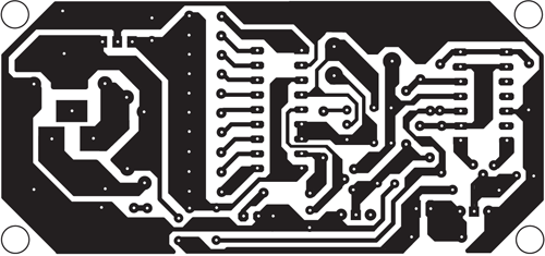
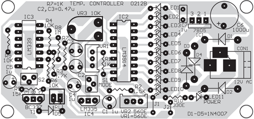
An actual-size, single-side PCB for the automatic fan controller for ACs is shown in Fig. 3 and its component layout in Fig. 4. Assembling the circuit on a PCB minimises time and assembly errors.
Use bases for ICs LM3914 and IC LM339. Enclose the assembled circuit in a suitable cabinet. On the PCB, provide suitable connectors for switches S1 and S2 and potentiometer VR3 to extend these out from the cabinet through cable.
The sensor is brought out from the cabinet with a two-core cable. LED1 through LED10, switches S1 and S2, and potentiometer VR3 are mounted on the front panel of the cabinet. LED1 through LED10 are marked with calibrated temperature values.
