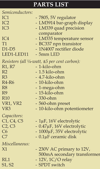
Calibration. Calibrate the automatic temperature controller before putting it into the AC’s circuit. Calibration is done for temperature control between 20ºC and 29ºC and temperature indication by LED1 through LED10.

First, with the help of a thermometer and digital voltmeter, set the temperature range to be indicated and controlled. Make sure that temperature sensor IC4 is free-standing in air, away from any source of heat, such as soldering iron or a heat-emitting lamp in the room.
Apply AC power to the circuit after finishing the construction. Do not connect motor to the unit yet. Using the thermometer, take the room temperature reading. Adjust preset VR2 such that the LEDs indicate a corresponding temperature. For instance, if the temperature is 24ºC, LED1 through LED5 should glow, while LED6 through LED10 remain off.
Next, connect the digital voltmeter across potentiometer VR3 and adjust preset VR1 such that the voltage reading is exactly 0.111V. This sets the temperature range by potentiometer VR3 between 20ºC and 29ºC.
The author is a regular contributor to EFY


