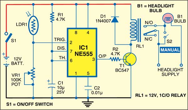
 Automatic headlamps are the latest convenience in today’s cars. These eliminate the need for the driver to manually switch on or switch off the headlamps in most driving situations. The automatic headlight switcher system reacts like the human eye to outside light levels and independently turns the lights on and off when needed. Such a system offers both safety and convenience.
This circuit can be particularly helpful when driving on roads with many tunnels, at twilight or sunset, and even in foggy, icy, stormy and rainy conditions. For example, when the car enters a dark tunnel, the driver will not have to fumble for the headlights switch. The car’s headlights will automatically switch on after sensing the poorly lit tunnel. When the car comes out of the tunnel, the headlights will switch off.
Automatic headlight switcher circuit
The circuit is built around timer NE555 (IC1), light-dependent resistor LDR1 and some discrete components. Potmeter VR1 is used to set the light sensitivity of LDR1. On sensing the darkness, LDR1 turns the headlights ‘on’.

Basically, an LDR is a resistor whose resistance decreases with increase in the intensity of the incident light. Usually, an LDR exhibits very high resistance in darkness and low resistance in the presence of ambient light. Thus a varying voltage drop can be obtained across it with changing ambient light conditions.
The LDR1 is connected to the trigger input (pin 2) of IC1.The output of IC1 is connected to the base of relay-driver transistor T1. The 12V supply voltage is connected to the circuit through switch S1. LDR1 and the 100-kilo-ohm preset constitute a voltage divider arrangement at pin 2 of IC1.
Circuit operation
Working of the circuit is simple. Enable the circuit using switch S1. When there is sufficient ambient light, the resistance of LDR1 remains low (a few hundred ohms). The voltage at pin 2 is greater than two-third of 12V. The output at pin 3 of IC1 remains low—stable state for monostable mode of operation—and the headlights of the vehicle connected to the normally-open (N/O) contacts of relay RL1 remain off.
When the ambient light decreases, the resistance of LDR1 shoots up to a few mega-ohms and the voltage at the trigger input (pin 2) of IC1 decreases to less than one-third of 12V. The output at pin 3 of IC1 goes high to energise relay RL1 and turn the headlights ‘on’. Switch S2 can be used to manually operate the headlights.
Construction & testing
Assemble the circuit on a general-purpose PCB and enclose in a small suitable cabinet such that the LDR sensor receives ambient light. Connect power supply switch S1 on the rear side of the cabinet to connect/disconnect the 12V car battery. Connect potmeter VR1 at the front side of the cabinet for varying the sensitivity to light as desired. Now your headlight circuit is ready for use.
The article was published in November 2011 and has been recently updated.
Feel interested? Check out other electronics projects.


The circuit is working good. But the only problem is, if the circuit works continuously for few minute, the voltage across the bulb automatically starts decreasing. I would be glad to know the reason behind!
I’m not an EE, but here’s my thought. The headlight is powered via a relay. A relay is either on or off, so I can’t see how whatever the circuit does can result in lower voltage.
What do we put at the headlight supply
You have to refer to your vehicle’s wiring diagram to figure that out.
Basically your standard highlights are powered by a relay just like the one in this circuit diagram. Whatever powers that relay, you can connect to as your supply.