


 This circuit can be used for automatic light control and 6V battery charging. It monitors the battery level and switches to charging and overcharging protection modes accordingly.
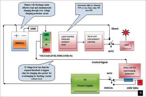
The block diagram is shown in Fig. 1. The circuit has four units: voltage-level indicator, automatic charging and overcharging protection, light control and power supply. When the battery voltage is less than the threshold value, the relay energises to connect the battery to the charging source. It also prevents overcharging by constantly monitoring the battery voltage level.
Circuit and working
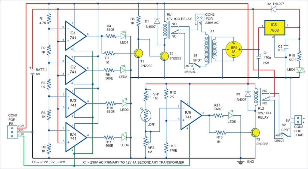
Circuit diagram for automatic light and overcharging control with a voltage-level indicator is shown in Fig. 2. It is built around five 741 operational amplifiers (IC1 through IC4, IC6), an 8V 7808 voltage regulator (IC5), a bridge rectifier (BR1), two 12V single-changeover relays (RL1 and RL2), three 2N2222 transistors (T1 through T3), three 1N4007 rectifier diodes (D1 through D3), a 6V battery (BATT.1) and a few other components.

Voltage-level indicator
Voltage-level indicators are built around IC1 through IC4 to indicate four different battery levels. IC1 through IC4 are used as comparators. These compare four different input voltages (5.5V, 4V, 2.7V and 1.4V) through voltage dividers formed by resistors R1 through R3, R6 and R9. The corresponding voltage levels are indicated using LED1 through LED4, respectively.
Battery charging
Automatic charging and overcharging protection circuit is built around transistors T1 and T2, transformer X1, bridge rectifier BR1 and voltage regulator 7808 (IC5). The output of IC1 is fed to relay RL1 through the inverter built around transistors T1 and T2. If battery voltage goes above 5.5V, the circuit de-energises relay RL1 to prevent overcharging. If voltage level is less than 5.5V, it energises RL1 to start battery charging.

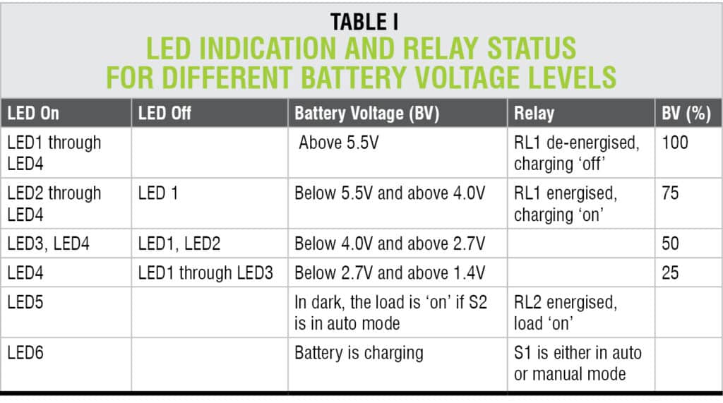
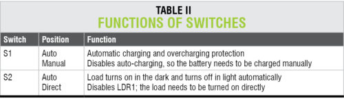
Switch S1 is used to charge the battery in either manual or auto mode. In manual mode, it provides direct path to charge the battery. But this mode has a drawback: When you forget to switch off S1, the battery will get overcharged. In auto mode, the battery is charged on-load or off-load with overcharging protection. Table I shows LED indication and relay status for different battery voltage levels.
Diode D2 provides unidirectional signal flow for battery charging from 8V DC supply.
Automatic light control. This unit is built around IC6, light-dependent resistor LDR1, transistor T3 and relay RL2. LDR1 provides control voltage to comparator IC6. You can control the sensitivity of LDR1 using potmeters VR1 and VR2. As per the setting of light intensity in LDR1, relay RL2 energises through T3 to switch on the load.
Switch S2 is used to activate the load in either direct or auto mode. In direct mode, the load can be switched on/off without LDR1. In auto mode, the load is controlled by LDR1. During night, the load will be ‘on.’ In daytime, the load will be ‘off.’ For detailed functions of switches S1 and S2, refer Table II.
Construction and testing
An actual-size PCB for automatic light and overcharging control with voltage-level indicator is shown in Fig. 3 and its components layout in Fig. 4. Assemble the circuit and enclose it in a suitable box. Connect ±12V power supply across CON1, 230V AC across CON2 and the load across CON3. Affix LDR1 at a suitable location such that sunlight falls on it directly.
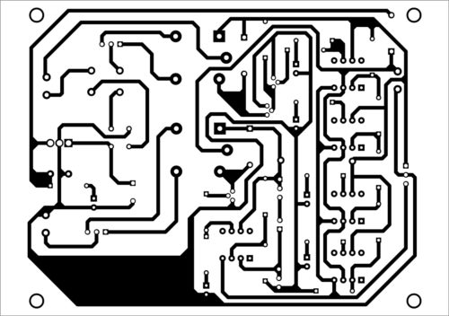
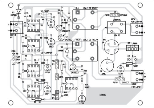
Download PCB and component layout PDFs: click here
For testing purpose, use a variable voltage source with a potmeter in place of the rechargeable battery (BATT.1). Connect one terminal of the potmeter to +6V and the other terminal to ground. Connect the wiper or mid terminal of the potmeter to pin 3 of IC1 through IC4. To indicate battery discharging, increase potmeter resistance. Check the status of LED1 through LED4. Also check switches S1 and S2 in both the modes.

Comment:PLEASE I NEED A SIMPLE PROJECT TITLE FOR A SYSTEM DEVICE THAT CAN HELP IN THE REGULATION OF ELECTRIC BULB-LIGHT EITHER TO INCREASE OR DECREASE THE AMOUNT OF ITS BRIGHTNESS(ILLUMINATION)
Please explain me about this project in detail.
Where this project is used?
Project name: automatic light and overcharging control with voltage level indicator
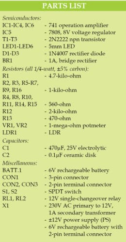
Please provide the parts list too. thanks you
Thank you for your comment. We have updated the article with the Parts List.
good even sir,you have my kudos.i have a question sir and it reads thus:why do you connect the NC terminal because all websites i have seen don’t usually connect it,ergo i want to know why thanks.