


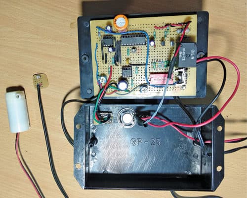
Here is a circuit for automatic plants watering, which can be undertaken every morning without any human effort. A sensor is used to detect ambient light and activate a pump motor to start watering the plants in the morning. You can set the watering time duration as per your requirement. The author’s prototype is shown in Fig. 1.

Circuit and working
The circuit diagram of the automatic plants watering system with melody is shown in Fig. 2.

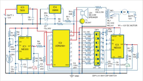
It is built around NE555 timer (IC1 and IC3), source driver UDN2981 (IC2), melody generator UM66 (IC4), 9V voltage regulator 7809 (IC5), npn transistor BC547 (T1), light-dependent resistor (LDR1) and a few other components.
NE555 (IC1) is configured as a monostable multivibrator. It acts as a one-shot pulse generator. The output pulse is available at its output pin 3 of IC1. Pulse begins when IC1 receives a low trigger input at pin 2, which falls below 1/3rd of its supply voltage.

Output pulse ends when the voltage on capacitor C1 equals 2/3rd supply voltage. That is, the width of output pulse depends on the time constant of resistor R2 and capacitor C1. This is determined by the following relationship:
T=1.1×R2×C1
UDN2981 (IC2) is the source driver. This 8-channel source driver is useful for interfacing between low-level logic and high-current loads. Its maximum output current is 500mA.
UM66 (IC4) is a melody-generator IC. 7809 (IC5) is a 9V voltage regulator, which converts 12V to regulated 9V output.
LDR1 along with potmeter VR1 and resistor R1 form the voltage divider at pin 2 of IC1. Trigger voltage is fed to IC1 through this voltage divider. When light falls on LDR1, its resistance and the potential difference between pin 2 of IC1 and ground decreases. In this condition, output pin 3 of IC1 remains high, which causes LED1 to glow. Sensitivity of LDR1 can be adjusted using VR1.
When input pin 1 of IC2 becomes high, its output pin 18 becomes high. This means, NE555 (IC3) pins 4 and 8 also become high. This leads pin 2 of IC3 to get grounded through C1 and its pin 3 to go high.
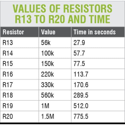
This causes LED2 to glow for a certain period of time, which is determined by the values of C5 and R13 through R20. The actual on-time output of IC3 is shown in the table below, assuming that value of VR2 is zero.
When you add the value of VR2 to R13 through R20, this on-time may increase accordingly. When C5 charges to 2/3rd of supply voltage, output pin 3 of IC3 goes low. Motor M1 for watering the plants and melody sound are off. DIP switch DIP1 is used for different time settings, as shown in the table.
When output pin 3 of IC3 is high, input pins 2 and 3 of IC2 become high through R7 and R8. This causes IC2 output pins 17 and 16 to become high. When output pin 16 of IC2 becomes high, current flows through R12 and relay RL1 is energised. Hence, a 12V DC pump motor fitted with a suitable pipe starts working. The amount of water for watering the plants depends on the type of DC pump motor used.
UM66’s maximum working voltage is 3.3V. A 3.3V Zener diode is used to provide the maximum required voltage. UM66 gets input from UDN2981, and its output is fed to the base of transistor T1 through R11.
Resistor R10 is used to set the threshold operation of the circuit. When UM66 is enabled, it produces a melody via speaker LS1. This melody sounds when the DC pump motor starts watering the plants.
IC 7809 is a fixed linear voltage regulator that maintains constant 9V supply to the circuit.
Construction and testing
An actual-size PCB layout for the automatic plants watering system with melody is shown in Fig. 3 and its components layout in Fig. 4. After assembling the circuit on the PCB, connect 12V batteries across BATT.1 and BATT. 2.
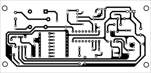

Download PCB and Component Layout PDFs :Click here
Fix LDR1 at a suitable location so that sunlight falls directly on it. Adjust VR1 for appropriate output. Select DIP1 switch in appropriate position for desired watering duration. Adjust VR2 for fine time adjustment. Rechargeable batteries are preferred for smooth working of the system. The proposed enclosure of the automatic plants watering system is shown in Fig. 5.
Nidheej R. Kozhuvanmackal is working as junior engineer (signals), Indian Railways. He has developed mine-detection and humanoid robots for security purposes and a solar-powered three-passenger three-wheeler vehicle. His interests include robotics and embedded systems
nice project i liked this