 This circuit counts and indicates up to nine persons present in the room and automatically locks the door and switches off lights as soon as they leave. It automatically switches on the lights when the first person enters the room. The circuit can be used as a power-saving device and a security device to prevent unauthorised entry in the room, especially in a business meeting room.
Circuit and working
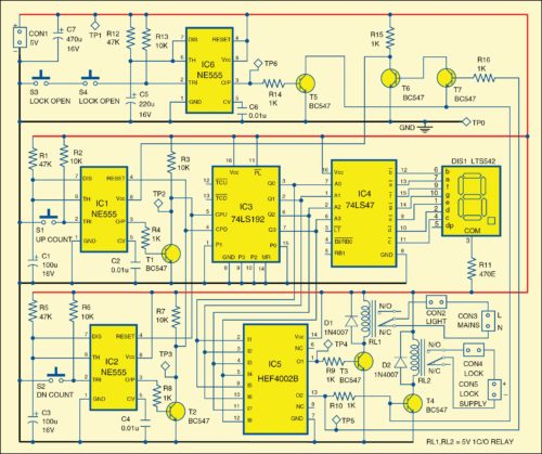
 The circuit, shown in Fig. 1, is built around three NE555 timer ICs (IC1, IC2 and IC6), an up/down BCD decade counter 74LS192 (IC3), a 7-segment display driver 74LS47 (IC4), 4-input NOR gate HEF4002B (IC5) and a common-anode 7-segment display LTS542 (DIS1). S1 and S2 are foot switches. S1 is installed under door-mat of the door used to enter the room, and S2 is installed under a door-mat just inside the room.
The outputs of IC3 change state synchronously with the low-to-high transitions on the clock inputs. Separate count up (CPU) and count down (CPD) pins of IC3 are used here. Its parallel pin 11 is made high and parallel data input pins 15, 1, 10 and 9, along with master reset pin 14, are made low in this circuit.
The outputs (Q0 through Q3) of IC3 are given to IC4 to drive display DIS1. Resistor R11 is used to limit the current flowing through DIS1.
Outputs of IC3 are also given to IC5. output O1 of IC5 is fed to relay-driver transistor T3 through resistor R9 to energise relay RL1. Light switches off when RL1 is energised. The second output O2 is fed to relay-driver transistor T4 to energise relay RL2 for locking the door. RL1 and RL2 energise simultaneously as inputs of 4-input NOR gate (IC5) are connected to both the drivers.
Download PCB and component layout PDFs: click here
Output O2 of IC5 is also given to the base of transistor T7 whose collector is connected to the base of transistor T6. When O2 of IC5 goes high, it locks the door and makes the Vcc pin 8 of IC1 low to stop further counting.
 To open the lock, press switches S3 and S4 (acting as security keys) simultaneously. The mononstable circuit built around NE555 (IC6) triggers and its output goes high for around 11 seconds and makes the base of transistor T4 low, via transistor T5. This action de-enegises relay RL2 to open the lock for a pre-defined time period based on the values of R12 and C5. At least one person should enter the room within this time period, otherwise it will get locked again. During this period, Vcc pin 8 remains high to enable IC1.
When each person enters the room and presses foot switch S1, counter IC3 advances by one count and display shows the number of persons in the room. On first person’s entry, the outputs O1 and O2 of IC5 go low, transistors T3 and T4 stop conducting and relays RL1 and RL2 de-energise to switch on the light and open the door lock.
Similarly, when they start leaving the room by enabling foot switch S2, counter IC3 reduces by one count and the display shows the number of persons present in the room. the outputs O1 and O2 of IC5 remain low, so light remains on and door remains open till the room is vacant.
Construction and testing
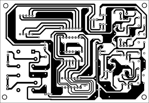
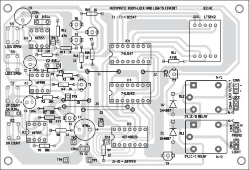
A single-side PCB for the circuit is shown in Fig. 2 and its component layout in Fig. 3. After assembling the circuit on PCB, enclose it in a suitable case. Switches S1 and S2 should be installed as explained earlier. The display can be installed on the door frame outside the room. Fix switches S3 and S4 at a suitable location such that you can press them simultaneously when needed.
Connect the door-lock assembly to relay RL2 contacts using external wires as shown in Fig.
1. Use a 2-pin connector each for connecting the light and lock assembly.
EFY note. Avoid entry of more than nine persons. Otherwise, at the entry of 10th person, the display will show ‘0,’ the door will get locked and the lights will switch off. If this happens, someone will have to press switch S2 from inside the room to open the lock and switch on the lights.
The author is a lab engineer at EFY Lab.


Can i have the code?
No code is required for this particular project.
is this project tested
Yes, this project is fully tested.
Is this project tested and verified?
Yes, this project is fully verified.
IC74LS192 used in the circuit is not available. Is there any equivalent IC available for 74LS192(synchronous up down decade counter)?
the pcb layout give is not the mirror image so guys if u are taking this project make sure u print the mirror of this image
Please check again carefully. The PCB solder side is given in mirror image.
I have problem in this project and I need help .When I made this circuit S1and S2 are didnt works.But all the circuit is good work .I didnt know what I do.
Sir, I thank you for this circuit it is interesting. Please sir I want to ask is there any way we can increase the number of persons more than nine even up to 20 person?
Please I need your help on how to construct PCB single sided board,
Thanks so much
For counting more than nine, you need to add display another 7-segment display and 74LS47. The current circuit and PCB are meant for nine people.