


An inverter turned into an emergency power system, which turns on when the mains supply fails, and more importantly doesn’t turn on when the main supply is available.
Can you give me a setup (emergency lighting system) where few of my lights will turn on when the supply from mains is unavailable, and more importantly, will not turn on when the supply from mains is available? That’s the question a reader asked us, who wanted to set up an emergency lighting system in his factory.
Our first reaction was “why doesn’t he use an inverter?” But then we realised that a normal inverter would mean that the emergency light would be turned on when the power from the main is there too—something the reader did not require. Quickly, we dished out an old inverter and made a few changes. We hooked our customised inverter to the wire powering his emergency light. It took us less than two hours to reconfigure the inverter, and we got a happier reader. Now we share with you the changes made by us, in the hope to get even more happy readers.

Construction of an Automatic On/Off Switching Circuit for the Inverter
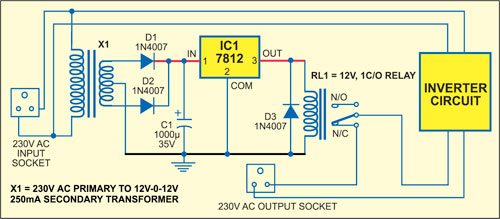
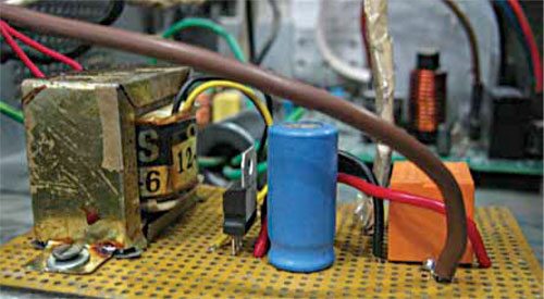
There are several ways to make the automatic on/off switching circuit for the inverter, but to make it simple and universal is slightly challenging. To make a universal circuit, a transformer, a regulator, a relay and a few discrete components are required. Fig. 1 shows the circuit of the home-made auto-on/off switch. The circuit assembled on a general-purpose PCB is shown in Fig. 2.
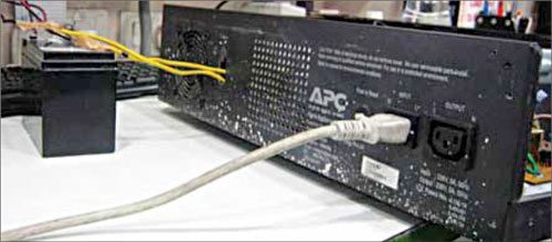
The circuit was tested on an APC 800VA inverter, which has 230V AC input and output sockets (refer to Fig. 3). The primary side of the transformer is connected to 230V AC input line of the inverter. The 12V-0-12V, 250mA secondary output of the transformer is rectified by two diodes, filtered by a 1000μF, 35V capacitor and regulated by IC 7812. The 12V regulated output is fed to a 12V change-over relay through which the switching action takes place.
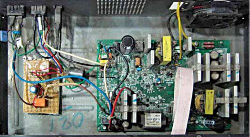
When the 230V AC mains is available, the relay energises and its common pole shifts to the normally-open (N/O) contact. The 230V AC output from the inverter is not available at its output socket. When mains goes off, the relay de-energises and its pole shifts towards the normally-closed (N/C) contact. The 230V AC output from the inverter is now available through the N/C contact. Fig. 4 shows a connection of the on/off switching circuit to the main inverter circuit.
If the inverter output load is known, this simple circuit can be inserted in any home inverter for auto-on/off switching. For a higher load, use a relay having a higher current rating.
This article was first published on 1 January 2012 and was recently updated on 29th January 2019.

i didn’t see battery terminals??
Would it be those 2 yellow wires in the photos, on photo shows a (7 Amps ?) UPS battery. Next photo the wires goto the inverter circuit?
Whi the 7812 ? Seems of no use to me, is just there spending power.
In this circuit, the switching action is done through a 12V DC relay. The transformer output cannot directly drive the DC relay. 7812 is a 12V DC output voltage regulator and is used to drive the DC relay.
How can I use two five pin relay as Auto switch for my inverter Please? Help with a simpler illustrated circuit diagram
How can I use two five pin relay as Auto switch for my inverter Please? Help with a simpler illustrated circuit diagram
You can connect another similar relay circuit across 7812 output pin