


The integration of a 555 timer and L293D motor driver in an automatic wiper control device presents a practical and efficient solution for enhancing driver safety and convenience.
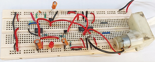
This system, with its simplicity and cost-effectiveness, can be a valuable addition to both three- and four-wheelers. Fig. 1 shows the author’s prototype on a breadboard.
Wiper Control Device – Circuit and Working
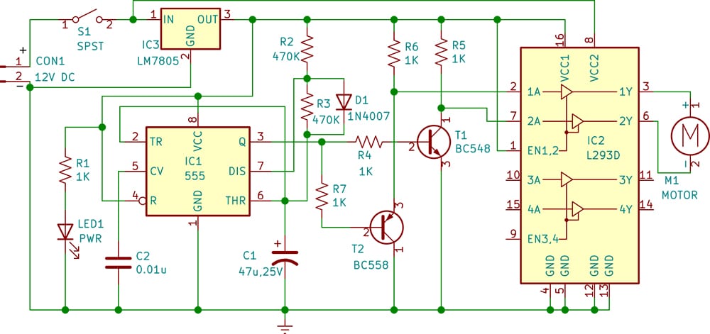
The circuit diagram of the automatic wiper control for three/four-wheelers is shown in Fig. 2. It is built around a 12V battery, timer 555 (IC1), motor driver L293D (IC2), 5V voltage regulator 7805 (IC3), and a few other components. LED1 acts as a power-on indicator when switch S1 is turned on, activating the wiper control system.

| L293D pin logic for motor direction | |||||
| Pin1 (EN1,2) | Pin2 (1A) | Pin7 (2A) | Pin3 (1Y) | Pin6 (2Y) | Motor Rotation |
| H | H | L | H | L | Clockwise |
| H | L | H | L | H | Anti clockwise |
The heart of the device is the 555 and L293D. The 555 timer (IC1) is a highly stable integrated circuit used for generating precise time delays or oscillation. It is wired as an astable multivibrator. In a traditional astable multivibrator circuit, a duty cycle of 50% or less cannot be generated.
To achieve a duty cycle of less than 50%, diode D1 is added across resistor R3, resulting in an output frequency of approximately 0.03Hz. The output of IC1 is given to transistors T1 and T2 to provide pulses, which are used as the inputs of IC2 to drive the L293D.

The L293D is a quadruple high-current half-H driver designed to provide bidirectional drive currents of up to 600mA at voltages from 4.5V to 36V. It is ideal for controlling the wiper motor, allowing for forward and reverse motion essential for wiper operation.
| Parts List |
| Semiconductors: IC1 – 555 timer IC2 – L293D motor driver IC3 – LM7805, 5V voltage regulator T1 – BC548 npn transistor T2 – BC558 pnp transistor D1 -1N4007 rectifier diode LED1 – 5mm LED (green/red) Resistors (all 1/4-watt, ±5% carbon): R1, R4-R7 – 1-kilo-ohm R2, R3 – 470-kilo-ohm Capacitors: C1 – 47µF, 25V electrolytic C2 – 0.01µF ceramic disk Miscellaneous: CON1 – 2-pin connector M1 – 12V geared DC motor 12V battery |
The output pin 3 of IC1 is connected to one end of two resistors, R4 and R7. The other end of resistor R4 is connected to the base of the NPN transistor T1 to provide a signal at pin 7 of the L293D, while the other end of resistor R7 is connected to the base of the PNP transistor T2 to provide a signal at pin 2 of the L293D.
Normally, when there is no rain, switch S1 should be off to disable the circuit, keeping the wiper motor inactive. When rain begins, switch S1 on to activate the circuit and initiate the wiper motor’s rotation to clean droplets from the vehicle’s windscreen.
The wiper rotates clockwise and anticlockwise based on the signal received at pins 2 and 7 of the L293D. These signals are provided by the output of timer 555 (IC1) through transistors T1 and T2.
The L293D output is connected to a geared motor to which the wiper is fitted. Enable pin 1 is connected to a high voltage of 5V (logic 1) to enable the driver. The wiper motor receives power and control signals to operate the wipers.
The L293D has 16 pins in total, as follows:
Pin 1 is Enable 1, which turns on/off the first H-bridge.
Pin 2 is input 1 (1A), which is the first input for motor 1. It is connected to the emitter of the PNP transistor T2.
Pin 3 is output 1 (1Y) for motor 1.
Pins 4 and 5 are grounded.
Pin 6 is output 2 (2Y) for motor 1.
Pin 7 is input 2 (2A), which is the second input for motor 1.
Pin 8 is connected to 12V to power the wiper motor.
These first eight pins of the L293D are used to control the first DC geared motor to rotate the wiper.
Similarly, there are two inputs and two outputs to control the second DC motor, though it is not used here. For more details, refer to the datasheet. See the table on previous page for the direction of motor rotation.
Construction and Testing
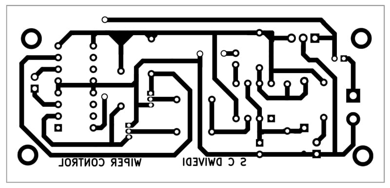
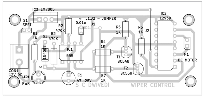
An actual-size, single-sided PCB layout for the automatic wiper control for three/four-wheelers is shown in Fig. 3, and its component layout in Fig. 4. After assembling the circuit on the PCB, enclose it in a suitable box. Fix LED1 and CON1 on the front side of the box.
Switch S1 should also be fixed on the front side of the box for convenient on/off control of the circuit. LED1 should glow when S1 is turned on after connecting a 12V battery or adaptor across CON1 to enable the circuit.
After assembling the circuit, enclose it in a suitable box and install the wiper on the motor shaft. Position the wiper to cover the maximum glass area when rotating. The automatic wiper control for three/four-wheelers is now ready for use.
Bonus: You can watch the video of the step-by-step tutorial of this DIY project below–
S.C. Dwivedi is an electronics enthusiast and circuit designer at EFY
