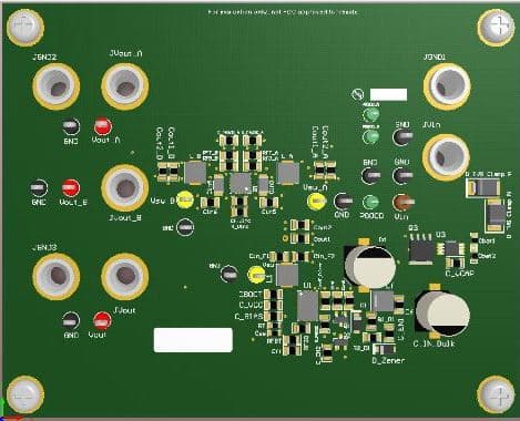
The automotive POL power supply is designed for protection against high-voltage spikes and reverse battery polarity, ensuring stable, efficient operation.

Automotive point-of-load (POL) power supplies are indispensable in the modern automotive industry, which is increasingly integrating electric and electronic systems into vehicles. These power supplies manage the variable voltage generated by an alternator, which fluctuates with the engine’s speed. They ensure the voltage is regulated and converted to stable levels suitable for various vehicle components. This includes basic functions like lighting and infotainment systems, as well as more complex systems such as autonomous driving technologies and electric powertrains. By providing the correct voltage and current to each device, POL power supplies maintain system reliability and performance. Their design also emphasizes high-efficiency power conversion, which minimizes energy loss as heat, crucial for extending battery life and reducing thermal loads in electric and hybrid vehicles.
Texas Instruments’ (TI) reference design for an automotive POL power supply exemplifies robust front-end protection within a compact setup. It is engineered to clamp down on rapid high-voltage spikes and maintain operation through such transient events. Additionally, the system is equipped to detect and shut down in response to reverse battery polarity situations. This design features a three-output configuration with two buck regulators sequenced to ensure the correct timing for power-on and power-off. It also incorporates an input pi filter to significantly reduce conducted electromagnetic interference (EMI). Operating with an input voltage range of 5 V to 36 V, the design delivers outputs of 3.3 V, 1.2 V, and 1.8 V, capable of supplying 2 A on the 1.8 V and 1.2 V outputs and up to 3.55 A on the 3.3 V output simultaneously.
The PMP15023 model represents a wide VIN to point-of-load solution that showcases the protective measures necessary to safeguard POL regulators against typical automotive fault conditions. It features three output voltages powered by two buck converters arranged in a sequenced series. The design incorporates components such as SMBJ26A-13-F and SMBJ14A-13-F for transient voltage suppression, enhancing its durability and reliability under variable conditions. Additionally, it includes reverse-polarity protection facilitated by a smart diode circuit, ensuring safe operation.
This smart diode circuit utilizes the LM74610-Q1 controller and an accompanying FET to maintain high impedance when the polarity is reversed, effectively preventing any reverse current flow from the output back to the input. The sequencing of the buck converters is managed by a subcircuit composed of two transistors, a bypass diode, a pair of capacitors, and series resistors. This arrangement guarantees that the primary regulator is activated before the secondary regulator and that the secondary deactivates before the primary, maintaining an optimal operational sequence and enhancing overall system stability.
TI has tested this reference design. It comes with a Bill of Material (BOM), schematics, etc. You can find additional data about the reference design on the company’s website. To read more about this reference design, click here.


