


 Nowadays maintenance free lead-acid batteries are common in vehicles, inverters, and UPS systems. If the battery is left in a poor state of charge, its useful life is shortened. It also reduces the capacity and recharge ability of the battery. For older types of batteries, a hygrometer can be used to check the specific gravity of the acid, which, in turn, indicates the charge condition of the battery. However, you cannot use a hygrometer for sealed type maintenance-free batteries. The only way to know their charge level is by checking their terminal voltage via a voltage analyser.
Battery Charger & Voltage Analyser Circuit
The circuit presented here can replenish the charge in a battery within 6-8 hours. It also has a voltage analyser circuit for quick checking of voltage before start of charging, since overcharging may damage the battery. The voltage analyser gives an audio-visual indication of the battery voltage level and also warns about the critical voltage level at which the battery requires immediate charging.The charger circuit consists of a standard step-down 12V AC (2-amp) transformer and a bridge rectifier comprising diodes D1 through D4. Capacitor C1 smoothes the AC ripples to provide a clean DC for charging the battery.

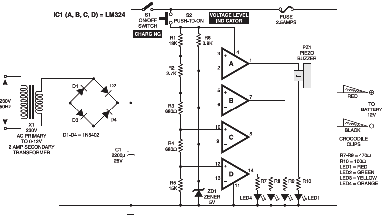
The battery voltage analyser circuit is built around the popular quad op-amp LM324 that has four separate op-amps (A through D) with differential inputs. Op-amps have been used here as comparators. Switch S2 is a push switch, which is pressed momentarily to check the battery voltage level before charging the battery.

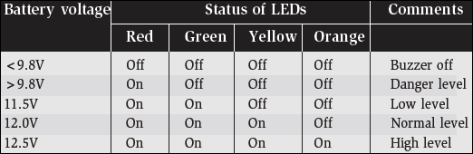
The non-inverting terminals of op-amps A through D are connected to the positive supply rail via a potential divider chain comprising resistors R1 through R5. Thus the voltage applied to any non-inverting input is the ratio of the resistance between that non-inverting terminal and ground to the total resistance (R1+R2+R3+R4+R5). The resistor chain provides a positive voltage of above 5V to the non-inverting inputs of all op-amps when battery voltage is 12.5V or more. A reference voltage of 5V is applied to the inverting inputs of op-amps via 5V zener diode ZD1.
Circuit operation
When the circuit is connected to the battery and push switch S2 is pressed (with S1 open), the battery voltage is sampled by the analyser circuit. If the supply voltage sample applied to the non-inverting input of an op-amp exceeds the reference voltage applied to the inverting inputs, the output of the op-amp goes high and the LED connected at its output lights up.
The article was published in March 2003 and has recently been updated.

Can this charger be used to charge 5 and 7 Ampere Lead acid batteries ?