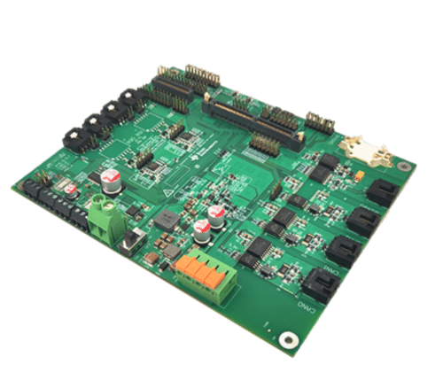
The design is a central controller for high-voltage Li-ion and LiFePO4 battery racks, with communication interfaces, a microcontroller, and safety features for industrial battery management.

Battery Energy Storage Systems (BESS) are increasingly integral in various settings, including residential, commercial, and industrial environments, as well as in grid energy storage and management. These systems, characterized by their high-voltage structures, vary in composition: multiple racks with stacked packs are standard in commercial and industrial settings. In contrast, a single rack is typically found in residential systems. Each rack, an integrated module, is crucial for the parallel connection of packs. Given their specific operational requirements for temperature, voltage, and current, monitoring and protecting the battery cells at the rack level is vital. This is where the Battery Control Unit (BCU) comes into play; a specialized controller is installed within the rack to manage the entire system’s energy efficiently.
TIDA-010253, a reference design from Texas Instrument (TI), is a comprehensive central controller for high-voltage Lithium-ion (Li-ion) and Lithium Iron Phosphate (LiFePO4) battery racks. It features driving circuits for high-voltage relays and various communication interfaces, including RS-485, Controller Area Network (CAN), daisy chain, and Ethernet. The design also includes an expandable interface for a humidity sensor, a high-voltage analog-to-digital converter (ADC), and a current sensor. Central to this design is a high-performance microcontroller, which aids in developing and testing applications, making it ideal for high-capacity battery rack systems.
In industrial applications, this design supports different types of battery systems, such as multi-module batteries with CAN or daisy-chain configurations and single-module batteries, each catering to specific industrial needs regarding battery management and connectivity.
The design’s interface is compatible with the Sitara MCU controlCARD. It includes robust drive channels for relay coils, daisy-chain communication, and reverse-polarity protection for enhanced safety and reliability.
The TMDSCNCD263 MCU operates and tests functions like power rail monitoring, wakeup, relay switch, watchdog (WTD), real-time clock (RTC), humidity sensor, and isolated communications (CAN, RS-485, Ethernet). The power supply design includes the LMR51440 buck converter, transforming a 24-V supply into a 5-V to power the MCU and other components. It also features a wakeup trigger circuit for the LMR51440 and the BQ79600 with TPS7A1601 support for reverse wakeup. The TPS7B8813 converts 5-V to 3.3-V for VIO and peripheral devices.
Peripheral devices such as the humidity sensor, RTC, and optional high-voltage ADC or current ADC are connected via an I2C bus. The HDC3020 measures humidity to prevent dew formation in an IP67 BESS container, while the BQ32002 with a coin cell battery generates local time for the MCU.
Basic insulation for CAN and RS-485 is achieved using UCC12050 and ISO1042 for isolated CAN and SN6505B and ISO1410 for isolated RS-485, supporting up to 500 Kbps data rates. The design includes the TPS3823-33 for timing supervision with a watchdog timeout of 1.6 seconds.
TI has tested this reference design. It comes with a Bill of Material (BOM), schematics, Gerber file, Printed circuit board (PCB) layout, computer-aided design/ computer-aided engineering (CAD/CAE) symbols, etc. You can find additional data about the reference design on the company’s website. To read more about this reference design, click here.


