


 This circuit utilises a low-cost 3W LED board to construct a battery-powered night lamp. This board consists of eight SMD2835 LEDs connected in series.
Branded LED bulbs have SMPS drivers and protection circuits for proper illumination. But some cheap LED bulbs have only capacitor power supplies and no protection circuits. In this project, 78S40 IC is used, which acts as a switching regulator system.
SMD2835 LED module
SMD2835 is a novel packaging structure with self-heat-sink design and high-efficiency LED module, widely used in the fields of general, commercial, industrial, city and automotive lighting, among others. Some of its features are given below.

Vertical structure
Chip direct conduction fins improve heat dissipation performance, which can withstand higher current (40-60mA).
Large heat-sink
Heat-sink is 2-3 times larger than SMD3528 with an excellent heat dissipation design.

Large light-emitting surface
This improves the efficiency of light up to 90 per cent.
Cost
Although SMD2835 is 25 per cent cheaper than SMD3528, the same luminous flux can be achieved using the former.
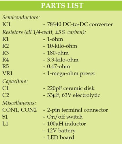
The circuit shown in Fig. 1 is built around 78S40 DC-DC converter IC (IC1), eight high-bright SMD2835 LEDs (from an old LED bulb) and a few other components. Here, IC1 is configured as a modified boost converter. It acts as both boost converter and constant current driver.
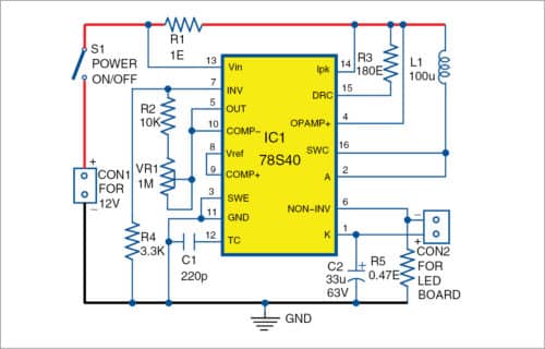
IC1 is in a 16-pin dual inline package that allows reference and a non-inverting input of the comparator to be pinned out. These additional features greatly enhance the flexibility of this part and allow the implementation of more sophisticated applications.
IC1, inductor L1 and the onboard circuitry of LED board perform voltage boosting operations. Current regulation is accomplished by monitoring the voltage drop across sense resistor R5, which is placed in series on the LED board. Since the maximum voltage across the sense resistor is less than one volt, the on-chip operational amplifier is used to increase the sense voltage for feedback.
Capacitor C1 determines the operating frequency of the circuit. Preset VR1 is used to control the brightness of the LED. Switch S1 is used to switch the LED board on/off.
Construction and testing of Battery-Powered Night Lamp
An actual-size PCB layout of the night lamp is shown in Fig. 2 and its components layout in Fig. 3. After assembling the circuit on the PCB, enclose it in a plastic case in such a way that connector CON1 is fixed at the rear side or inside the case. Fix CON2 on the top of the case for connecting the LED board.
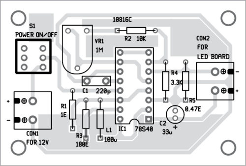

Download PCB and component layout PDFs: click here
A ready-made inductor can be used in place of L1. For better efficiency, an external Schottky diode can be used instead of the internal one. IC 34063 along with an op-amp can be used in the circuit in place of IC1. For peak current greater than 1.5A, an external transistor must be used to avoid device failure.
After assembling and connecting the 12V battery and LED board, your circuit is ready to use.
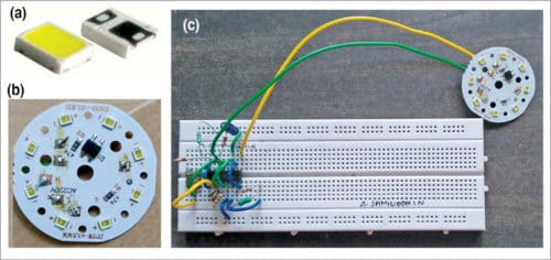
Use S1 to switch the night bulb on/off. Fig. 4 shows the SMD2835 LED, the LED board with SMD2835 and the author’s prototype on the breadboard.

Very good content