


 LM317T and LM337T ICs are well-known, low-cost adjustable voltage regulators capable of delivering up to 1.5A current output with power dissipation of up to 20W. LM317T produces a positive output voltage, while LM337T produces a negative output voltage.
It is useful to have a bipolar power supply with LM317T and LM337T producing symmetrical output power. However, adjusting both output voltages simultaneously is an issue.
The usual solution is to build a tracking voltage regulator with operational amplifier, which tracks the positive or negative output of the power supply. But here power supplies and other parameters of the operational amplifier can be limiting factors for the required power output.

Another solution is to use a stereo potentiometer (potmeter) to adjust both the output power supplies simultaneously. Good-quality stereo potentiometers have small differences (of about ±5%) between the two outputs. If this difference is too large, you may use additional potentiometers to adjust the output voltages to exactly the same value.
Here we present the circuit of a bipolar power supply with LM317T and LM337T adjustable regulators. The circuit provides the facility to adjust output voltages more precisely with individual potentiometers. Also, output voltages can be adjusted from near-ground levels, not from the typical ±1.25V.

Circuit and working
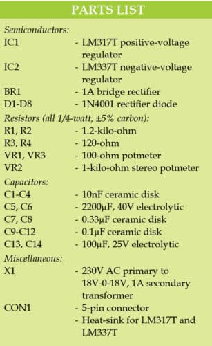
Circuit diagram of the bipolar power supply with LM317T and LM337T is shown in Fig. 1. It is built around an 18V-0-18V step-down transformer (X1), 1A bridge rectifier (BR1), variable positive-voltage regulator LM317T (IC1), variable negative-voltage regulator LM337T (IC2), eight 1N4001 diodes (D1 through D8) and a few other components.
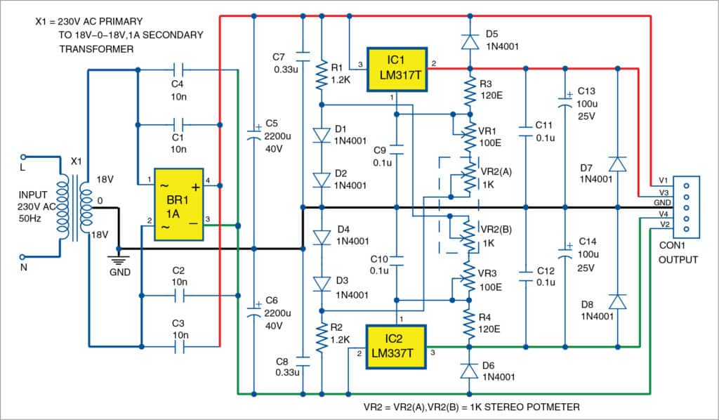
Fig. 1: Circuit of the bipolar power supply with adjustable regulators
The 230V AC mains is fed to the primary coil of transformer X1. You can choose the transformer as per your maximal output voltage and current requirements. Here, transformer X1 is used to produce regulated output voltage up to ±15V.
Bridge rectifier BR1 should be rated at least 1A. Main filtering capacitors C5 and C6 should be at least 2200µF, 40V. The unregulated positive voltage is applied to pin 3 of IC1, while the unregulated negative voltage is applied to pin 2 of IC2.
Regulated power supply section includes LM317T, LM337T and stereo potmeter
VR2(A)+VR2(B) for simultaneous adjustment of the output voltages. The output voltage of LM317T normally starts from around 1.25V and that of LM337T from around -1.25V. Here, D1 and D2 create positive reference voltage of around +1.3V, which is used as the offset for IC2. Also, D3 and D4 create negative reference voltage of around -1.3V, which is used as the offset for IC1.
That is why output voltages V3 and V4 can start from almost ground levels. If you need better stability, use reference diodes for 1.2V, such as LM385-1.2, instead of ordinary diodes D1 through D4. Diodes D5 through D8 protect regulators from reverse voltages.
Heat-sinks
Mount IC1 and IC2 on appropriate heat-sinks that have thermal resistance value of less than 4°C/W. The maximal power dissipation can go up to 10W if you need output current above 0.5A at the lowest output voltages. When calculating the required heat-sink size, consider that the maximal power dissipation of LM317T and LM337T in TO-220 package is 20W, junction-to-case thermal resistance is 4°C/W and maximal junction temperature is +125°C.
Construction and testing
An actual-size PCB layout for the bipolar power supply is shown in Fig. 2 and its components layout in Fig. 3. After assembling the circuit on the PCB, connect the secondary terminals of transformer to points marked X1 in the PCB. Fix potmeters VR1 through VR3 on the front side of the cabinet so that you can adjust the voltages easily.
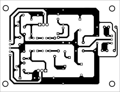
Fig. 2: PCB layout for the bipolar power supply
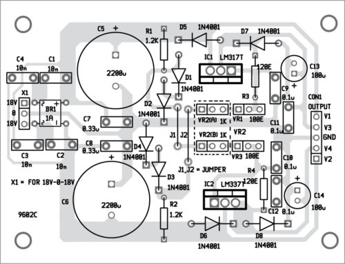
Fig. 3: Components layout for the PCB
Download PCB and component layout PDFs: click here
For testing, connect the circuit to 230V AC mains. Next, at the output connector, connect load resistors of 33 to 51 ohms with power dissipation of at least 10W (preferably above 20W). Set wipers of VR1 and VR3 to their middle positions. By varying stereo potmeter VR2(A)+VR(B), adjust the output voltage to the required voltages, e.g., around ±10V. Vary VR1 and/or VR3 in case further adjustment is required in the output voltage. Now if you connect and disconnect the loads, output voltages V3 and V4 should change slightly around the initial value of ±10V.
This article was first published on 25 January 2018 and was updated on 27 March 2020.

Can the current capacity be increased upto 5 Ampere by adding bypass transistors like 3055 with this regulators ? Please suggest transistors in that case with circuit ?