Creating a Bluetooth-controlled device with an Arduino Uno and an HC-05 Bluetooth module enables control of lights or even relays to manage AC appliances wirelessly using an Android smartphone.
Communication between the smartphone and the Arduino Uno is facilitated by the HC-05 Bluetooth module, which provides an easy and cost-effective method to integrate remote control functionality into various devices.
By utilising MIT App Inventor, it is possible to develop a custom app that sends commands to the Arduino, allowing complete control over connected devices, such as toggling lights on or off.

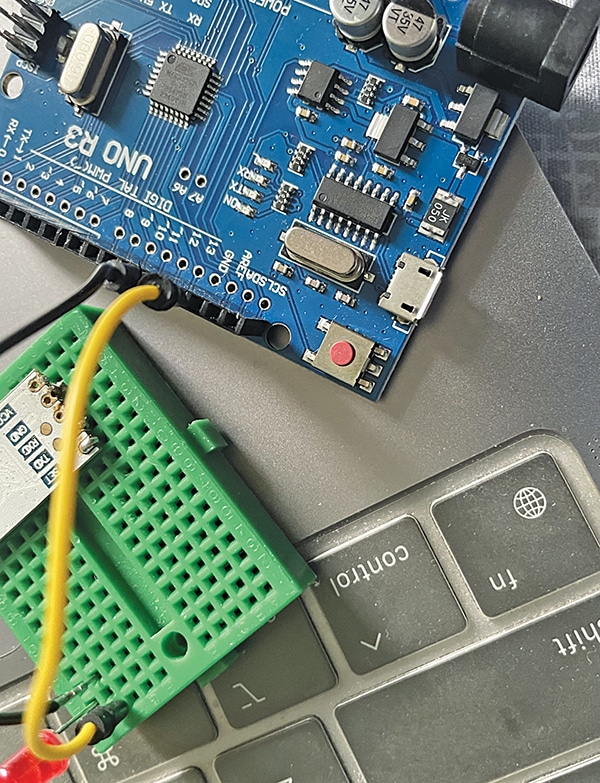
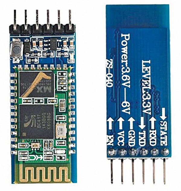
Whether controlling an LED or an AC device, this setup demonstrates a simple yet powerful application of Arduino and Bluetooth technology. The author’s prototype is shown in Fig. 1. The list of components required for the device is detailed in the Bill of Materials table. An image of the HC-05 Bluetooth module is shown in Fig. 2.
| Bill of Materials | |
| Item Name | Quantity |
| Arduino Uno with USB cable | 1 |
| HC-05 Bluetooth module | 1 |
| Breadboard | 1 |
| Resistor 1-kilo-ohm (R3) | 1 |
| Resistor 2-kilo-ohm (R2) | 1 |
| Resistor 330-ohm (R1) | |
| 5mm LED | 1 |
| Connecting wires | As required |
Circuit Diagram
Fig. 3 shows the circuit diagram of the Bluetooth control through mobile. It is built around an Arduino Uno (MOD1), an HC-05 Bluetooth module (MOD2), and a few other components.

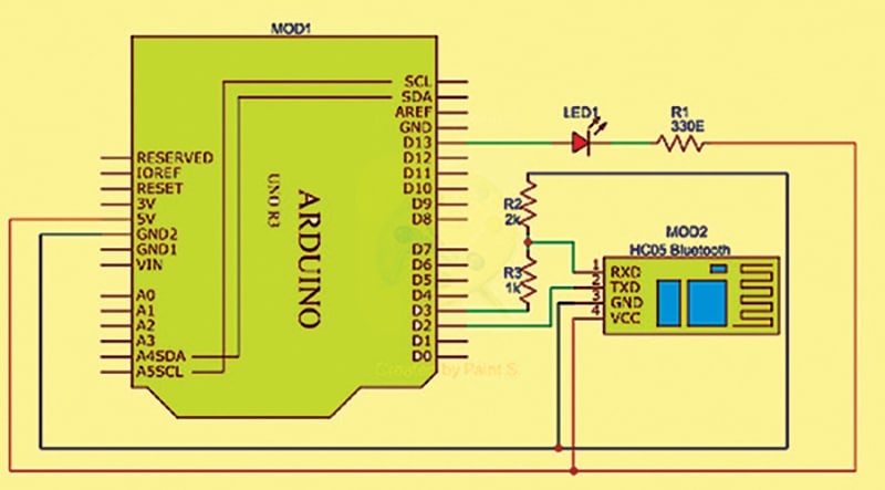
In the HC-05, the pin EN stands for enable. This pin, when pulled low, disables the device. When connected to 3.3V or left free, it enables the device. In this setup, it is left free so that it is always enabled. The HC-05 requires a VCC in the range of 3.6V to 6V.
Since the Arduino Uno does not provide 3.6V, it is connected to 5V (do not connect to 3.3V as it is too low). The GND of the HC-05 is connected to the GND of the Arduino Uno.
For software serial communication between the HC-05 and the Uno, the library `SoftwareSerial.h` will be used. Pins 2 and 3 of the Uno will act as Rx and Tx. Connect Rx (pin 2) directly to TXD of the HC-05.
Since pin 3 cannot be connected to RXD (as the HC-05 expects 3.3V logic levels), a potential divider with 1k and 2k resistors is used to connect RXD to pin 3.
The ‘State’ pin of the HC-05 indicates whether the device is paired with another Bluetooth device. When paired, this pin goes high. In this setup, this pin is not used, so it is left free.
The HC-05 also includes an LED that blinks rapidly when not paired and blinks slowly when paired with another device.
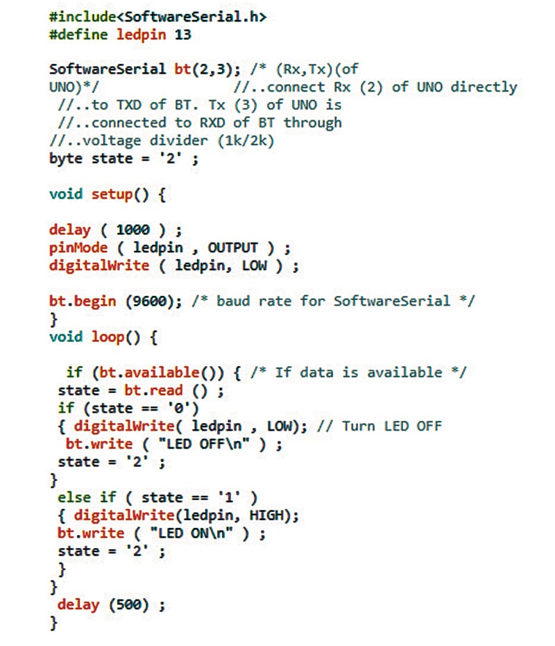
Software
The code is written in Arduino IDE. First, the pin for the LED or relay is defined, and then the serial read function is used to receive the command. The command is then used to perform functions like turning the device on or off. Fig. 4 shows a snippet of the source code.
This device requires Bluetooth to send commands to the Arduino. Either Kodular or App Inventor can be used to create the app. In this case, MIT App Inventor is used.
It is assumed that the reader is familiar with the article titled ‘Make a Digital Clock on Your Android Mobile Device,’ published in the January 2024 issue of Open Source For You magazine.
Power up the HC-05 and Arduino combination. Open the Android phone and navigate to settings>Bluetooth> available devices.
If ‘rarely used devices (1)’ appears below this, click on it. The HC-05 may be listed. Click on it and pair it. The pairing code is either 0000 or 1234. Close Settings.
MIT app inventor: Log in to the MIT App Inventor as mentioned in the earlier article. It is recommended to use the same words to ensure easy comparison between the screenshots provided and the user’s screen.
Click on Projects>Start new project. Give the device a name. For instance, ‘Bluetooth_Control’ (avoid using ‘Bluetooth’ as there is already an app with that name on the mobile). In the Properties pane, change the title to ‘Bluetooth Control.’
In the Palette pane, go to User Interface>ListPicker and drag it to the viewer pane. In the properties pane, change the height to 10 percent, width to Fill Parent, and text to Scan.
In the palette pane, go to Layout >HorizontalArrangement and drag it to the Viewer pane, below ListPicker1. In the Properties pane, change the height to 10 percent and width to Fill Parent.
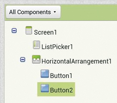
Once again in the Palette pane, drag User Interface >Button to the HorizontalArrangement box. Drag another button and place it next to the first button. In the All-Components pane, they will appear as Button1 and Button2 below HorizontalArrangement1, as shown in Fig. 5.
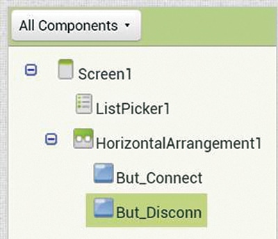
Give meaningful names to Button1 and Button2. Select Button1. At the bottom of the All Components pane, there is a Rename button. Click it. A window will open where a new name can be typed. Rename it as ‘But Connect’.
Now, select Button2 and rename it as ‘But_Disconn’. It will appear as shown in Fig. 6.
Select ‘But_Connect’ again. In the Properties pane, change the height to Fill Parent, width to Fill Parent, and text to Connect. Now select But_Disconn and change the height to Fill Parent, width to Fill Parent, and text to Disconnect.
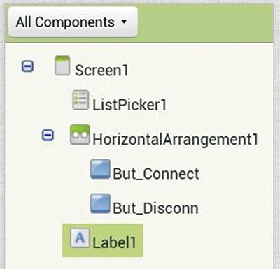
In the Palette pane, under User Interface, drag Label and place it in the Viewer Pane below HorizontalArrangement1 (i.e., Connect and Disconnect buttons). Change the properties of Label1 as follows: Height to 10 percent, width to Fill Parent, and text to Not Connected. Set Text alignment to Centre. See Fig. 7 to check how to change the properties of a label.
Drag HorizontalArrangement (Palette>Layout) and place it under Label1 in the Viewer pane. Change the properties to height of 10 percent and width to Fill Parent. Drag button (Palette>User Interface) and place it in this HorizontalArrangement. Drag another button and place it next to the first one. Rename these buttons as ‘But_ON’ and ‘But_OFF’ respectively.
In the ‘All Components’ pane, select But_ON. Change the properties, with height set to Fill Parent, width to Fill Parent, and text to ON. Now select But_OFF and change the properties, with height set to Fill Parent, width to Fill Parent, and text to OFF.
Drag another button and place it below HorizontalArrangement2 (i.e., ON and OFF buttons). In the ‘All Components’ pane, rename it as But_Close. In the properties pane, change the height to 10 percent, width to Fill Parent, and text to CLOSE.
In Palette>Connectivity, drag BluetoothClient and drop it into the Viewer pane. It will appear as a non-visible component.
Download the extension TaifunTools and import it into the device. Drag and drop it into the Viewer pane as a non-visible component.
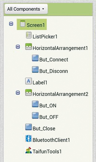
The final screenshots are shown in Fig. 8. If there is any deviation from these, correct it or repeat the steps. Pay careful attention to the relative positions in the screen above. This completes the Designer part of the device.
The blocks mode: Click on ‘blocks’ shown in the top-right corner of the screen. The left-hand side of the screen will resemble Fig. 9.

If the screen does not resemble Fig. 10, then corrections or adjustments are required in designer mode.
Click on Screen1 and select when Screen1.Initialize block. Drag it match it with when Screen1.Initialize block. KeepScreenOn.Further Click on ListPicker1 and select when ListPicker1.BeforePicking.
Again, click on ListPicker1, and this time, select set ListPicker1.Elements.to and match it with BeforePicking. Click on BluetoothClient1 and select Bluetooth1.AddressesAndNames and match it at the open end.
Click on ListPicker1 again and select When ListPicker1.AfterPicking. Click on Label1 and select Set Label1.Text.to and match it. Click on Built-in>Text and select the empty box (the topmost one). Drag it and match it with the open end. In the empty box, type ‘Press Connect.’
Click on But_Connect and select when But_Connect.Click.
Go to Built-in>Control and select the if.. then.. else block and match it.
Click on BluetoothClient1 and select call Bluetooth1.Connect and match it with the if block.
Click on ListPicker1 and select ListPicker1.Selection and match it with the Address socket.
Click on Label1 and select set Label1.Text.to and match it with the Then block. At the open end, match an empty text box. In the box, type ‘Connected.’
In the else block, match a set Label1.Text.to block, add an empty text box, and type ‘Failed to Connect.’
Click on But_Disconn and select When But_Disconn.Click. Click on Call BluetoothClient1.Disconnect and match it.
Below that, match set Label1.Text.to and add a text box with the text ‘Disconnected.’
Click on But_ON and select When But_ON.Click. Click on BluetoothClient1 and select Call BluetoothClient1.SendText and match it.
Take an empty text box and match it at the open end. In the text box, type ‘1.’ Repeat the above procedure with But_OFF, and in the text box, type ‘0.’
Finally, click on But_Close and select When But_Close.Click. Now, click on an empty space in the viewer pane and start typing Close.
A list will open, and from the list, select Close application. Match it in the empty socket.
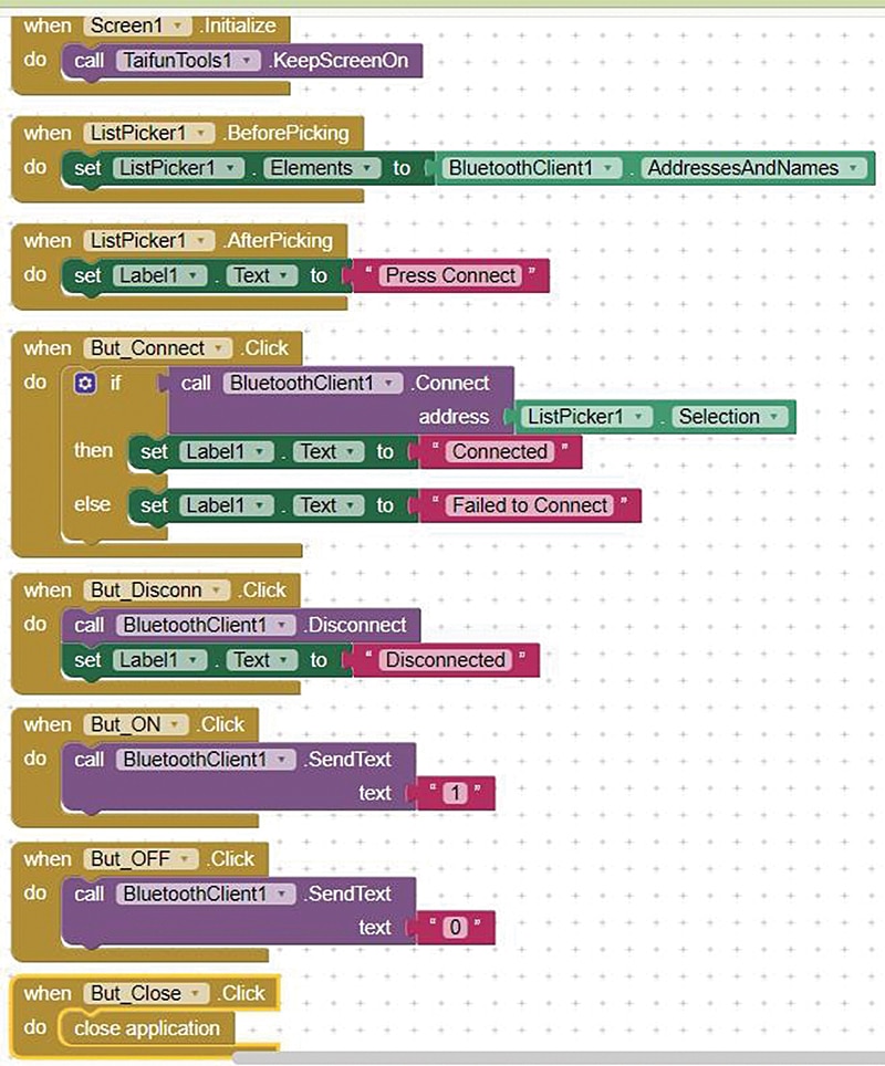
This completes the design setting of the device. The complete picture is shown in Fig. 10.
It is now time to install the program on the mobile. Go to Play Store, download, and install MIT AI2 companion (if it has not been done already).
Now go to the computer screen, click on Build (at the top of the screen), and select Android App (.apk). The program will compile, and a QR code will appear. On the mobile, open MIT AI2 Companion and scan the QR code.
Follow the instructions on the screen (ignore warnings – there is no malicious code here) and install the app. (Ensure both the mobile and computer are on the same Wi-Fi network.)
Now, turn on the HC-05 Arduino combination and press Scan on the mobile. A new screen will appear, showing the name ‘HC-05’ and its MAC address. Click on it, and the screen will return to the original, allowing ‘Connect’ to be pressed.
Also Check: Arduino Projects that you must try
Testing
Power the Arduino using USB. If the screen that appears when Scan is pressed is blank, check and adjust the app permissions. Go to Settings and ensure Bluetooth is enabled.
Also, go to Settings> Apps>Permissions>Other Permissions>Apps and grant all necessary permissions to the app. (Some mobiles may have slightly different names, but the procedure is similar.) This completes the procedure for Bluetooth control through an Android mobile.
Hemakumar K., with 27 years of teaching and other experience, retired as an Associate Professor from the Government College of Engineering, Kannur, Kerala.