


Brushless DC motor drivers are fuelling the rise in BLDC motor. But their control usually requires rotor position information for selecting the appropriate commutation angle. Normally, a Hall Effect sensor is used to sense rotor position.
But in cost sensitive applications, a sensor-less commutation scheme is often desirable. The brushless DC motor driver circuit described here uses a DRV10866 driver IC to drive a small BLDC fan, without using any position sensors. A BLDC fan’s speed can be varied smoothly, without the usual steps associated with a normal AC fan.
Table of Contents
Brushless DC Motor Driver circuit
Fig. 2 shows the circuit of a sensor-less BLDC motor driver. The circuit is built around an NE555 (IC1), a DRV10866 (IC2) and a few other components.

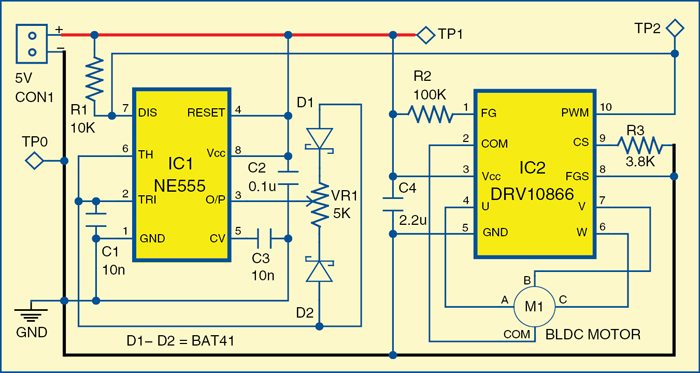
DRV10866 driver IC from Texas Instruments is used to drive a small three-phase BLDC motor (M1). The circuit is of a three-phase, sensor-less motor driver with integrated power MOSFETs having drive-current capability up to 680mA peak.
DRV10866 is specifically designed for low noise and low component-count fan-motor drive applications. A 150° sensor-less back emf scheme is used to control the three-phase motor.

A 100k pull-up resistor (R2) is used at pin 1 of IC2. Pins 2, 4, 7 and 6 of IC2 are connected to common, phase A, phase B and phase C of the BLDC motor, respectively. Pin 10 of IC2 is connected to pin 7 of IC1 to get the pulse-width modulated (PWM) signal from IC1 to control the speed of the BLDC motor.
The output signal (PWM) is available at IC1’s pin 7 (DIS) and not from the usual output pin 3 of the IC. The 25kHz (approx.) PWM signal’s duty cycle can be adjusted from 5% to 95% using potentiometer VR1.
The speed of the BLDC motor can be controlled by varying the duty cycle of the PWM signal. Turning VR1 counter-clockwise lowers the duty cycle which, in turn, lowers the speed of the motor, and vice versa.
Construction and Testing
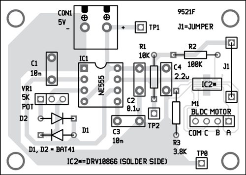
A single-side PCB for the brushless DC motor driver is shown in Fig. 4 and its component layout in Fig. 5.
Assemble the circuit on the recommended PCB to minimise assembly errors. IC2 should be fitted on solder side of the PCB.
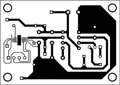
Download PCB and Component Layout PDFs: click here
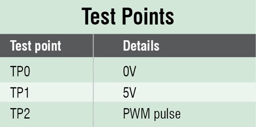
After assembling the components, connect a 5V DC supply to CON1 connector. To test this brushless DC motor driver circuit for proper functioning, verify correct 5V supply for the circuit at TP1 with respect to TP0. Turn VR1 clockwise or counter-clockwise to increase or decrease the speed of the motor.
For more exciting circuit projects: click here
The author is a B.Tech (Electronics and communication) from GGSIPU, New Delhi
This article was first published on 6 February 2017 and was updated in 2026.

We want to purchase PCB for railway carriage BLDC Fan 110 V DC 400 mm sweep.
Requided PCB Mfg. address.
Required PCB for Railway carriage BLDC Fan 110 V DC 400mm sweep.
Please contact us on 09881203351
We can supply.
@ R Bose : Sorry, pcb isn’t avaialble with us. For other projects, you may visit kitsNspares.com where you will get PCB and components of more than 400 projects.
what modification needed for 12 volts
I think BLDC is the future of electric motors even for the industries. Refinement of the drive circuits for highest efficiencies is very essential.
I need to develop a E rickshaw controller for up to 2000 Watt motor.Please let me know the cost of project.
Is there a way to hack the circuit of the driver so I can make the brushless motor as a generator? I want to create my own mobile phone charger.
I WANT BLDC CONTROL DRIVE FOR 1200MM SWEEP CEILING FANS WITH 360 PLUS RPM.
IF ANY HAVE CONTACTS OR DESIGN THEN CONTACT ME ON [email protected].
Dear Friend
Where can I buy this DRV10866 IC?.
Could you please give me the address.
I wanted your circuit diagram “circuit idea” published in your magazine i.e. the year of 1970 to 1980 Can you help me Sir?
Kindly elaborate your query.
How does the number of poles effect the torque and speed of the dc motor. For eg. If the number of poles are 6 vs. 12?
Why 150 deg ? Shouldn’t they be spaced 120 deg. Apart? Please elaborate.
Where can you get the specific pcb?
Dear Neville,
Sorry, PCB is not available with us. For other projects, you may visit kitsNspares.com where you will get PCB and components of more than 400 projects.
Regards
what modification needed for 12 or 18 0r 24 volts motor ??
Dear Shah,
Circuit is designed for 5V,3 phase BLDC motors because input voltage range of DRV10866 driver IC is between 1.65 V to 5.5 V.
Regards
Hello Sir,
Can get Simulation file.
I am using proteus 8 professional