


A cell phone Signal jammer is an electronic device that blocks the transmission of signals between a cell phone and a base station.
By using the same frequency as a mobile handset, the signal jammer creates strong interference in communication between the caller and receiver.
It is effective in blocking the transmission of signals from networks including UMTS, 3G, CDMA, GSM, and PHS.

DIY Cell Phone Signal Jammer – Components Required
| COMPONENT | USAGE |
| Resistor R1 | Emitter Loading |
| Resistor R2 | Base Biasing |
| Capacitor C1 | Frequency Generation |
| Capacitor C2 | Feedback |
| Capacitor C3 | Feedback |
| Capacitor C4 | Noise Reduction |
| Capacitor C5 | Coupling |
| Capacitor C6 | Coupling |
| Capacitor C7 | Decoupling |
| Transistor Q1 | Amplification |
| Inductor L1 | Frequency Generation |
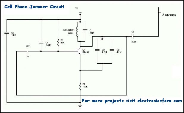
Cell Phone Signal Jammer Circuit
For any jammer circuit, it’s essential to have three important subcircuits.
- RF amplifier
- Voltage Controlled Oscillator
- Tuning circuit
These 3 circuits, when combined together form an efficient cell phone jammer circuit.
Cell Phone Signal Jammer Working
- RF amplifier circuit comprises transistor Q1, capacitors C4, C5, and resistor R1. This RF circuit amplifies the signal generated by the tuned circuit. The amplified signal is given to the antenna through capacitor C6. It blocks DC and allows only the AC component of the signal to be transmitted.
- When transistor Q1 is turned ON, the tuned circuit at the collector turns ON. The tuned circuit consists of capacitor C1 and inductor L1. This acts as an oscillator with zero resistance. It produces very high frequency with minimum damping.
- When the circuit is ON, voltage is stored in the capacitor. Once the capacitor is completely charged, it allows charge to flow through the inductor. When current flows through the inductor, it stores magnetic energy corresponding to the voltage across the capacitor. At a certain point, the inductor reaches its maximum and the charge or voltage across the capacitor turns to zero.
- Now the magnetic charge through the inductor decreases and the current charges the capacitor in opposite or reverse polarity. The process repeats and after a while, the inductor charges the capacitor and becomes zero.
- This process runs till internal resistance is generated and the oscillations stop. RF amplifier feed is given through capacitor C5 to the collector terminal before C6. The capacitors C2 and C3 generate pulses in a random fashion (noise) at the frequency generated by the tuned circuit.
- The RF amplifier boosts the frequency generated by the tuned circuit. The frequency generated by the tuned circuit and the noise signal generated by the capacitors C2 and C3 is combined, amplified, and transmitted.
Mobile Frequency Jamming Calculation
Mobile phones operate at different frequency bands in different countries. For Canada, the 1900 MHz band is the primary band, particularly for urban areas. 850 MHz is used as a backup in rural areas. The USA uses 850 and 1900 MHz bands, depending on the area.
Europeans tend to use the GSM 900 and 1800 bands as standard. Middle East, Africa, Asia, and Oceania also use these frequency bands. In Russia and some other countries, local carriers have licenses for 450 MHz frequency to provide CDMA coverage.
The use of different frequencies makes it difficult to have a jammer for all frequencies. However, the below-mentioned formula can be used to calculate the required values.
F = 1/(2*pi*sqrt(L1*C1))
Depending on the frequencies you need to block, the values of the inductor (L1) and capacitor (C1) can be altered.
For example, if mobile phones in your area work at 450 MHz, you need to generate 450 MHz with some noise to act as the blocking signal.
Now the cell phone receiver will not be able to understand, which signal to receive. We have successfully blocked cell phone signals.
Here, 450MHz is the tuning frequency. Cell phone jammers for other frequency ranges are designed similarly. However, the signal range is very weak. Thus, this circuit works only for a range of 100 m.
Note
- This circuit can block signals only within a 100-meter radius.
- Usage of this type of circuit is banned and illegal in most countries.
- This circuit is also used in TV transmission and remote-controlled toys.
- If the circuit is not working properly, try increasing the resistor and capacitors values in the circuit. Use the formula given above.
- The power supply for the circuit should not exceed 3 Volts.
We have more such interesting DIY Electronics Projects for you.
Note: The cell phone jammer is an untested prototype circuit and is banned in several countries. Keeping in with those regulations, we might not be able to help you out with the exact values.
This article was first published on 17 October 2017 and recently updated on August 2023.

the bf494 is a npn transistor not a pnp as in the circuit diagram
Thank you for your input, the article is updated now.
YAGI UDDA antenna
Your right
What is the name and Model of Antena?
This circuit will not Jam any cellphones.
Can you pleas elaborate that why it doesnt work?
yes totally worng..
1microfarad capacitor with 63 v can work on 3v battery.
if you have a pspice file for this circuit then please send on my mail i.d
It is an informative article. As of now, we don’t have any PSpice file for this circuit.
I think Pspice would not work in this kind of jamming signal
At which terminals we have to connect the supply
Dear Krishna, Since this is banned in some areas, this is just a prototype to give you an example.
is this working
Hi Peter, this project is just a prototype.
HI THIS WORKING PETER
what’s the values of resistors and remain
Sir did it work
Can this circuit will work in india ?
Dear Blue zee,
This is only a prototype circuit, as of now we do not have the source code for this article.
It is int working
This project is only a prototype
Pls say wat is meant by prototype . And will the circuit wrk
Prototype is just an idea for the circuit. You can create the circuit as per your liking with measurements from anywhere. We can’t guarantee that the project would work but the concept is sound.
hey man just send me a copy of the full file
Dear Adarsh, this is just a prototype circuit. All the required information is already provided in the article.
I want to learn concept of this jammer for my mini project can u please help me with it
it does not work
give me the exact diagram
Dear Adarsh, this is a prototype to give you an idea of the circuit. We do not own the verification of the circuit.
Bro you have circuit of Mobile jammer
Yes , please send any one of the working circuit ( only for BSc project )i request you to send quickly.
Hey send me the working circuit
did you get the working model ?
Bro r u check it?
another circut please sent my mail id
Comment:
Good day pls. give me a simple diagram of a signal jammer with parts that are available in the market…
I intend to use it for blocking wifi & moble phone signals…
You can’t jam WiFi signal, Because WiFi is work on 2.422 GHz so you can’t generate this frequency from tank circuit by component which is available in market.
please tell me what the output of C6 Then is possible to simulate this circuit in proteous 8.0
is it possible to simulate on proteous
yes..but if the project needs coding u need to code before you can simulate
sounds and looks like a good idea. My daughter is doing some home work and needs literature on making phones. I found your work sound easier I hope it will help her.
Thank you for your feedback.
we want the full details about jammer with coding
Is this circuit needs any coding….can i use this circuit directly…. Will. You pls sent me ..the full details and circuit diagram…
On…
[email protected]
Whats the use of this if it is not working. I need the the working circuit plz. Can u upload it??
i have the working circuit but when i give it to you, you have to be sending me message to direct you on it
You can send an email to [email protected].
Salau. can you send me it please [email protected]
Salau, can you please send the working circuit on [email protected]. I shall be highly grateful.
Hi, please can you help me with the circuit
give me a cell Wi-fi breaker circuit ……
thanks , It will be very useful article me
Thank you for your feedback.
this cicruit is use
The circuit is not working…..xo …..is their any alternativeeee to that
I need a exact circuit diagram of cell phone jammer circuit
Is this circuit working and getting a range of 100m?
Comment:the 22nh and 15 pf capacitor connect serial manner the we get the booster circuit it is true or false
someone tell me how can i make a 22nH inductor ? do i use coil or just a normal copper wire
Can this circuit be made using bread boards ???
Plzz help asap!!
Comment: please i need a working circuit diagram for this in Nigeria. its my final year project.
emeka. please can we communicate. [email protected]
Did you manage making this signal jammer project
If already have a jammer, how to improve its working range?
I bought a jammer on perfectjammer.com , but I found that the interference range is not enough. Can I improve the interference range by modifying the circuit?
HOW Can we advanced this circuit to get some work
I really like your teaching on how to make cellphone jammer. Thank you so much.
But I need your help to complete my project. P/s how can I get the jammer complete circuit?
Thanks.
thanks for this info
Hi ,
Here , whats the model of the antenna you had used in your prototype circuit ?
I am looking for acircuit diagram for a transistor servo circuit complete. In my country you won’t find servo or its ICs.
Please any one explain the concept of mobile jammer and how it works?? Please Wednesday I have seminar, so please give explanation… Quick
What type of antena used ?
Hi it’s sanjid from Uk would u able to make me mobile signal jammer
An if u do how much will u charge me
Thanks
Thanks sir
for good information
I am amazed at the people commenting on here. If you have read the 20+ times that the team has said this is simply a concept a.k.a. =
a prototype. And if you do not know what a prototype is and yet have the ability to post the question, you then also have the ability to search the internet for the answer. This is not for entry level or rookie skill level. If there is anything unclear to you here then this is simply above you skill level. You need senior to expert level experience and knowledge of Electrical, RF, PCB and/or telecom. Engineering
Exactly, and what makes me wonder is why they are all in such dire need of such a device?
They should not be messing around with RF transmitter circuits in the first place. This is a fine example of people, “knowing just enough to be dangerous!”.
They may as well take an old microwave oven apart, grab a hold of the magnetron, and aim it at their victim and fire it up!
Opps, maybe I shouldn’t give any ideas like that! Lol ?
something helpful
thanks
It block 4g network
What about CDMA, W-CDMA and LTE,etc.. will it work properly because these technologies uses spread spectrum rather than a single frequency.
I want to create one for 2300 mhz. So to increase the frequency only L1 and C1 has to be changed or any other components as well like R1,C7,etc ?
Looking forward for your answer. Please Do help.
heyyy hii have u done this? i need ur help plz give me fullly details about it annnnd as this is my project i need to completee soon lease help me in completing this….and finnally did it work
The transistor bf 494 is working on 250mhz.if you want to make rf oscillator for 450mhz then you first replace the transistor. As a basic circuit this is a good circuit.
The operating frequency of transistor bf 494 is 250 MHz,if you want to make rf oscillator for 450mhz then you replace the transistor. As a learning purpose the circuit is good.
Plz send component and it’s value
Hello,
I think there is a mistake and the colector should not be connected to ground, otherwise the DC will be short circuited -assumming an ideal coil of zero resistance.
Note for dummies: I finally got it… the line from C5 to C6 is not connected to ground -it crosses over but there is no black dot 🙂
Yaaah u are really right of the circuit diagram u just display but it is too noisy asas compared to how u said the c4 reduceses noise but rather the sound more inflicted within the circuit. I did I project which will be able to provide a mosque with LEDs display .after some time I got to know dat , mobile phones ring and bells in the mosque where by we are praying .
So I decided to make a stop to it by making it work so jamm the signal range within the mosques not any other place , so I made several research about how to jamm mobile phones , so I made research and it brought me through success and I was able to make it, but unwantedly it affects the microphone player system within the mosque with made the speaking more difficult and the sound was not spicing out well but rather created a radio active signal noise piiiiiiiiiiiin
Will u plz send your circuit diagram
Assalamu Alaikum brother, can you please send me your working mobile phone jammer for a project that am doing. May ALLAH bless you
i need a working model project on physics can you suggest some ideas
in general how can we increase the frequency of the device
Plz any one say it’s practically working or not ????.
You say the target freq. for the circuit is 450 Mhz but for the given inductor and capacitor C1 it would generate a ~277 Mhz signal, am I missing something?
Hi,
The line above Q1 is it connected?
The line under R2 is it connected?
Hello there. I want to make a mobile signal jammer like this for a autistic child. He spends his time most of on useing mobile phone and he is start to act rude and attacker. He playing games and watching videos online. Actually that videos have violence and more. So the kid becoming to dangerous person. All i want make a simple and tiny circuit for block phone cell in 2 squaremeters. Can you please help me ? i tried this circuit but this doesn’t work. if you help me, we will be greatful to you. thanks alot. with all respect.
You say the target freq. for the circuit is 450 Mhz but for the given inductor and capacitor C1 it would generate a ~277 Mhz signal, am I missing something? Or how can i amplify it to 450mhz thanks
Reply
Since resistor and capacitor values are not given and or listed. Good luck making a “working” prototype. It’s like playing Russian roulette.
The Circuit looks more line a FM Mike. Except for the feed back component, C5, all are almost identical.
Sir, you have said that it is just a prototype.According to my knowledge, even it is a prototype but it must be true and should work.
But why are you saying that i don’t guarantee for working.
Is it wrong circuit??
Hi Aman, these projects are not tested by EFY teams, that’s why we can’t guarantee the final output.
after building this how to increase the range if we need to
The jamming system transmits adequate power radio signals to cut-off communications between cell phones and cellular base-stations.Mobile Jammer is available in different models depending upon the output power.
Upon activating Cell phone jammer, all idle phones will indicate “NO SERVICE”. When the cell phone jammer is turned off, all cell phones will automatically re-establish communications and provide full service.
By solving the equation I found 277 MHz frequency how can you say that this circuit is working for 450 mhz frequency
If I increase or decrease the range, then what should I change ? And how can I know what should be the appropriate value of components for that specific range ?