


 A tachometer measures the rotation speed of motors and other machinery. There are various types of tachometers. Described here is a digital non-contact type tachometer using a proximity sensor.
Circuit and working
The circuit diagram of the Arduino-based tachometer is shown in Fig. 1. It is built around Arduino Uno board (Board1), inductive pnp-type normally-open (NO) proximity sensor, a 16×2 LCD (LCD1), optocoupler PC817 (IC1) and a few other components.
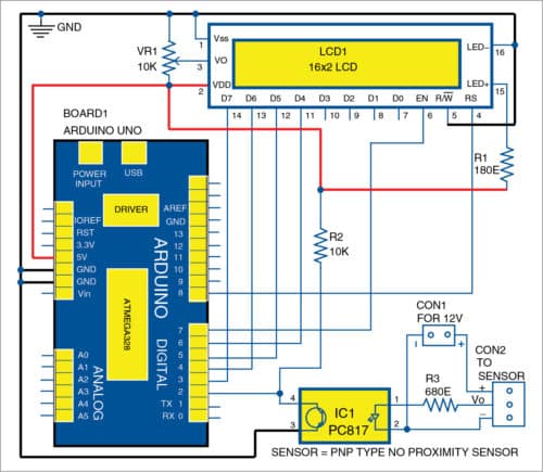
A metal such as a bolt head is fixed on the shaft of the rotating object. Whenever the metal crosses the sensor during rotation, the sensor generates a pulse at its output. The program in Arduino counts the number of pulses received for one second and converts into rotations per minute (RPM). The rpm count is updated every second and is displayed on LCD1.

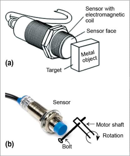
Proximity sensor
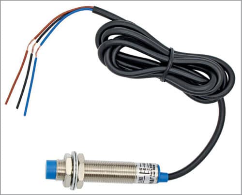
A proximity sensor detects objects nearby without any physical contact up to its nominal range. The maximum distance that the sensor can detect is its nominal range. A proximity sensor can have high reliability and long functional life because of the absence of mechanical parts and physical contact between the sensor and the target/object. A pnp-type NO proximity sensor used in this project is shown in Fig. 2.
The program (tachometer.ino) is written in Arduino programming language. Arduino IDE is used to compile and upload the program to Arduino board.

Select the correct board from Board->Tools menu in Arduino IDE, select COM port and upload the program (tachometer.ino) through the standard USB port of the computer.
Construction and testing
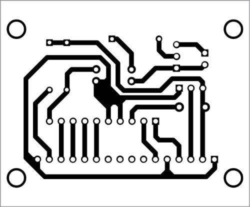
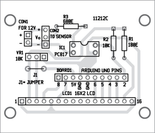
An actual-size PCB layout of the Arduino-based tachometer is shown in Fig. 3 and its components layout in Fig. 4. Assemble the circuit on the PCB. Connect Arduino Uno to the PCB using external jumper wires. Power supply for Board1 is provided by the computer’s USB port.
Download PCB and Component layout PDFs: click here
Sensor setup
After assembling the circuit on the PCB, connect output of the proximity sensor across connector CON2 and connect an external 12V DC across CON1 for the sensor to operate. Place the proximity sensor near the object whose rpm is to be measured, as shown in Fig. 5. When the metal target comes near the proximity sensor, the inbuilt LED on the rear side of sensor blinks. This indicates that the sensor is sensing the metal target (object).
RPM measurement
You cannot read the rpm directly because of resolution. Resolution is based on the number of metal target(s). The rpm can be measured using the following relationship:
rpm = [interrupt count per second x 60(secs per min)]/number of metal targets
If metal target is 1, resolution will be 60rpm; if metal target is 10, resolution will be 6rpm; if metal target is 60, resolution will be 1rpm, and so on. One metal target was used during testing at EFY Labs. As metal target increases, resolution also increases.
Download source folder
Also, check DIY Tachometer built with a Microcontroller.
A. Samiuddhin is B.Tech in electrical and electronics engineering. His interests include LED lighting, power electronics, microcontrollers and Arduino programming.

Hi
If we count number of pulses:n and total time:T for those pulses, better resolution is feasible
When I extract zip folder found an empty folder named Build non contact type digital tachometer please give the link or arduino ino file for the code
thankink you.
Syed Mazhar Momin
hello sir, i’m stuck in doing simulation and coding that can detect malfunction of car rear lights(for signal lamps,brake lamps and presence lamps). the project will use arduino mega and the malfunction will be display by using lcd 2×16. really hope that you can help me. ~Thank you.