

Controller Area Network (CAN) is a robust vehicle bus standard designed to enable microcontrollers and devices to communicate with each other without a host computer. Originally developed for automotive applications, it is now used in many other fields, such as industrial automation, medical equipment, and building automation.
In this project, we aim to design the smallest and lowest-cost CAN bus module using the TJA1050 IC. The TJA1050 is a high-speed CAN transceiver, interfacing the CAN protocol controller and the physical bus. Our design will include only the essential components to keep costs low and ensure a compact form factor.
Bill of Materials
| Component | Quantity | Description |
|---|---|---|
| TJA1050 | 1 | High-speed CAN transceiver |
| C1 | 1 | 100 nF capacitor for decoupling |
| C2 | 1 | 4.7 µF capacitor for stabilization |
| Resistors | As needed | Various for pull-ups/downs |
| Connectors | As needed | For CANH, CANL, power, and GND |
| PCB | 1 | Custom designed for this project |
CAN Bus Module Circuit Design
Core Components
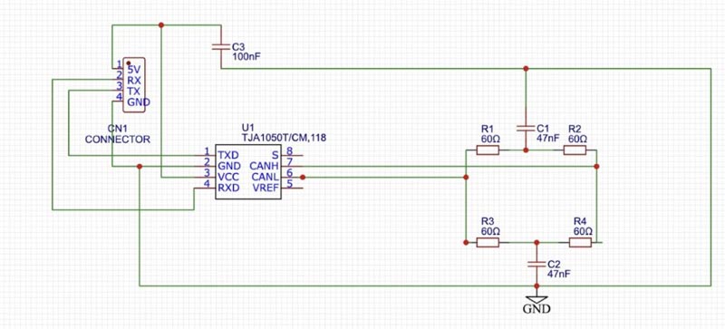
The core of the CAN bus module is the TJA1050 IC. Below is a basic schematic of the circuit:
- Power Supply: The TJA1050 operates at 5V. Ensure a stable 5V supply is available.
- Capacitors:
- C1 (100 nF): Placed close to the VCC pin of the TJA1050 for power supply decoupling.
- C2 (4.7 µF): To further stabilize the supply voltage.
- TJA1050 Pins:
- TXD: Transmit data input from the CAN controller.
- RXD: Receive data output to the CAN controller.
- CANH and CANL: Connect to the CAN bus lines.
- VCC and GND: Power supply pins.
- STB: Standby pin (optional connection for low-power modes).
CAN Bus Module PCB Design
After successful prototyping, design a compact PCB layout:
![]()

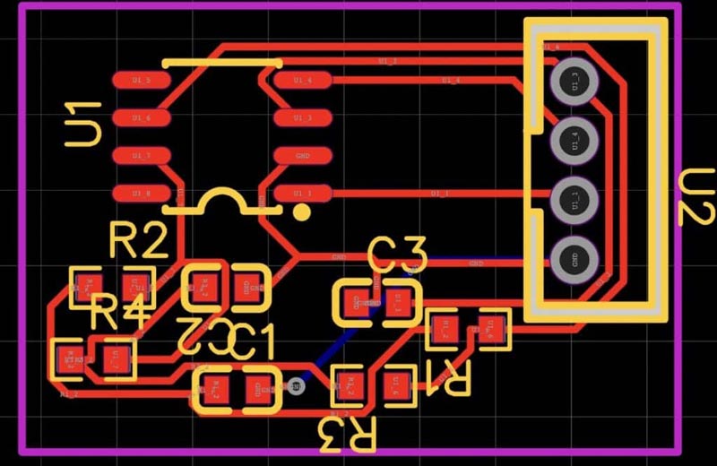
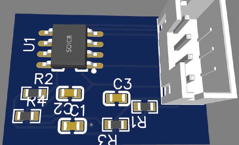
- Component Placement: Place the TJA1050 in the center, capacitors nearby, and connectors at the edges for easy access.
- Routing: Ensure power and ground traces are thick enough to handle the current. Minimize the length of the signal traces for better signal integrity.
- Layers: Use a single or double-layer PCB to keep costs low.
Testing
- Power Supply Verification: Check the 5V supply at the VCC pin of the TJA1050.
- Communication Test: Connect the module to a CAN bus network and use a microcontroller to send and receive messages.
- Signal Integrity: Use an oscilloscope to check the CANH and CANL signals for proper differential signaling.
- Functional Test: Run a sample application to verify the module’s functionality within the CAN network.
By following this guide, you can design and build a compact, cost-effective CAN bus controller module using the TJA1050 IC. This module will be suitable for a variety of applications, from automotive to industrial automation. The key is to ensure minimal component usage while maintaining high performance and reliability. This approach not only reduces costs but also simplifies the design and manufacturing process.