Here is an easy-to-build car anti-theft guard. The circuit, shown in Fig. 1, is simple and easy to understand. When key-operated switch S2 of the car is turned on, 12V DC supply from the car battery is extended to the entire circuit through polarity-guard diode D5. Blinking LED1 flashes to indicate that the guard circuit is enabled. It works off 12V power supply along with current-limiting resistor R4 in series.
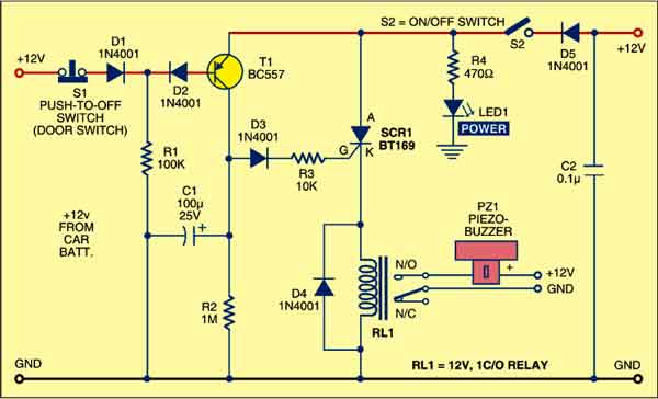
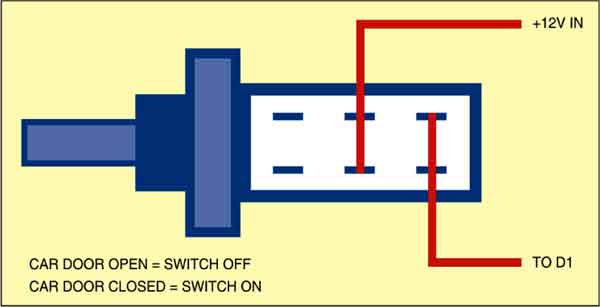
When the car door is closed, door switch S1 is in ‘on’ position and 12V power supply is available across resistor R1, which prevents transistor T1 from conducting. In this position, anti-theft guard circuit is in sleep mode.
When someone opens the car door, switch S1 becomes ‘off’ as shown in Fig. 2. As a result, transistor T1 conducts to fire relay-driver SCR1 (BT169) after a short delay introduced by capacitor C1. Electromagnetic relay RL1 energises and its N/O contact connects the power supply to piezobuzzer PZ1, which starts sounding to indicate that someone is trying to steal your car. To reset the circuit, turn off switch S2 using car key. This will cut-off the power supply to the circuit and stop the buzzer sound.

Assemble the circuit on a general-purpose PCB and house in a small box. Connect switch S1 to the car door and keep piezobuzzer PZ1 at an appropriate place in the car.