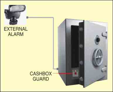
Most thefts happen after midnight when people enter the second phase of sleep called ‘paradoxical sleep.’ Here is a smart security circuit for your cash box that thwarts the theft attempt by activating an emergency beeper. The circuit can also be used to trigger any external burglar alarm unit.
The cash box guard circuit (shown in Fig. 1) is built around IC CD4060 (IC1), which has an inbuilt oscillator and divider. The basic oscillator is configured by a simple resistor-capacitor (R-C) network. IC CD4060 divides this oscillator frequency into binary divisions, which are available as outputs.
In light, reset pin 12 of IC1 remains low, which enables the oscillator built around IC1. However, in the dark, it making all the outputs low. This also stops oscillations of the internal oscillator.

Working of the circuit is simple. If the cash box is closed, the interior will be dark. Hence in the dark, the light-dependent resistor (LDR1) resets IC1 and it stops oscillating and counting. At the same time, pins 13 and 14 of IC1 go low. So neither the piezobuzzer (PZ1) sounds, nor the relay (RL1) energises, indicating that the cash box is closed.
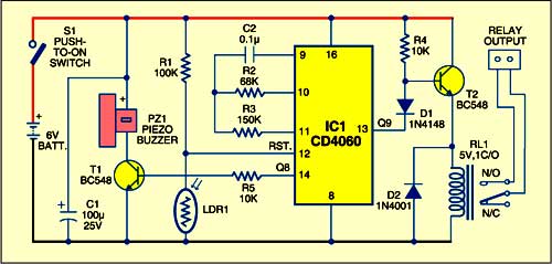
If someone tries to open the door of the cash box, light-most probably from the burglar’s pen torch -falls on LDR1 fitted into the cash box. As a result, LDR1 conducts and pin 12 of IC1 goes low. IC1 starts oscillating and counting. With the present timing R-C components (at pins 9, 10 and 11), the output timing at pin 14 of IC1 is two-three seconds. Hence pin 14 of IC1 goes high for two seconds after the door is opened and goes low for another two seconds. So the piezobuzzer (PZ1) sounds for two seconds and then falls silent for the following two seconds. This cycle repeats until the cash box is closed.

An optional relay is added for a remotely located audio/visual alert system. For that, a relay driver circuit built around npn transistor BC548 (T2) is used. The relay is energised by the output from pin 13 of IC1 for about four seconds after the door is opened and then de-energised for the following four seconds. You can use this relay to activate another remotely located audio/visual alert system.
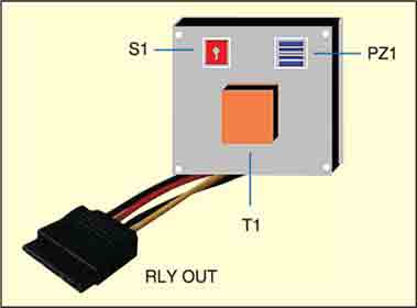
After assembling the circuit on a small PCB, house it in a small tamper-proof box (refer Fig. 2) leaving a little window for LDR1 and a small opening for the piezobuzzer (PZ1). Now fit the unit inside the cash box (refer Fig. 3) with LDR1 pointing towards the door of the cash box.
EFY note. 1. The relay latching facility can be added to the circuit by replacing transistor T2 with a suitable silicon-controlled rectifier such as BT169.
2. By changing the value of resistor R1, you can adjust the light detection sensitivity of the circuit.
3. If you want to use a 3-pin piezobuzzer device, remove buzzer-driver npn transistor T1 and connect trigger pin of the buzzer directly to pin 14 of IC1. Also connect the positive and negative terminals of the buzzer to respective positive and negative points of the circuit.
4. Photo-transistor 2N5777 can be used in place of the 10mm LDR1.
5. The complete kit for this circuit is available with Kits’n’Spares.