


With this simple clock controlled timer, you will never again miss your favourite TV or radio programme. The TV or radio will switch on automatically at the time preset by you and will remain ‘on’ until the power supply fails or is disconnected.
Clock controlled timer circuit
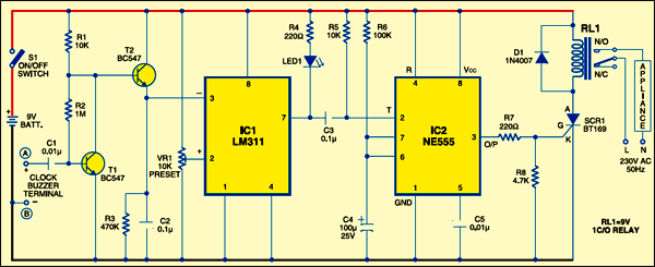
The circuit uses the AC signals generated at the buzzer terminals of an alarm clock. The AC signals are amplified by transistors T1 and T2 and the amplified output from the emitter of T2 is fed to the inverting input of negative-voltage comparator IC LM311 (IC1). The non-inverting input of IC1 gets a presettable voltage through preset VR1. The inverting and non-inverting inputs of LM311 are different from other op-amps and it outputs sink current through pin 7 or source current through pin 1.
Circuit operation
When pin 3 of IC1 is at a higher voltage than pin 2, its output sinks as indicated by LED1. This gives a short negative pulse to the monostable wired around timer NE555. Resistor R5 keeps trigger pin 2 of IC2 high. The short-interval monostable outputs a high signal for a brief period to the gate of SCR1 (BT169) and relay RL1 energises. The latching action of SCR1 keeps the relay pulled even when the output of the monostable turns low. The relay can be de-energised by disconnecting the supply to the circuit via switch S1.

Construction & testing
The circuit works off a 9V battery. Assemble it on a general-purpose PCB and enclose in a suitable cabinet. Provide an AC outlet in the cabinet to switch on the appliance using the circuit. As mentioned earlier, the input signal is obtained from the buzzer terminals of the clock. Remove the small buzzer of the clock and connect point ‘A’ to the positive terminal and point ‘B’ to the negative terminal of the buzzer. Connect the mains AC terminal outlet to the normally-opened (N/O) contact of relay RL1. So when the relay energises, 230V AC operates the connected appliance.
Set the desired time in the clock by adjusting the alarm set-up and switch on the circuit. When the set time reaches, the appliance will switch on automatically. The circuit can also be connected to digital clocks.

The article was first published in February 2007 and has recently been updated.