
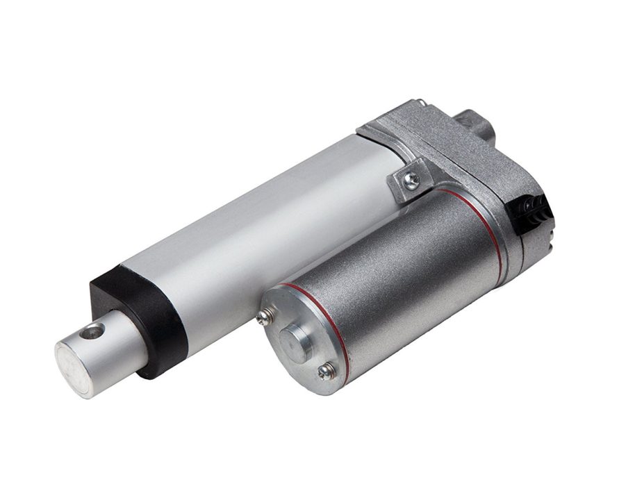
There is a wide application of linear actuator where one wants to move something, but they do not want to physically get involved in moving it. There are quite a number of ways to control linear actuators depending on the application and the user experience required. These are the key aspects determining the setup and the way this setup will operate.
It is common for most movements to involve manual control using remote control or a rocker switch. It is however paramount, that the system has some form of intelligence to improve the level of efficiency involved.
Microcontrollers, and relays in some cases are required for the intelligence in the system setup. Here we use an Arduino, a popular microcontroller board that provides an ease of setting up. There are other alternatives, but Arduino has a lower learning curve.
The parts required for the project setup are Arduino UNO, progressive automation PA-14-6-50, 12V 5A power supply, female power plug, small flat head screwdriver, pololu VNH5019 motor driver rated at 12v5a and SPDT relays. These are easily available and are part of a setup that is easy to build and comes up with a powerful automated system.
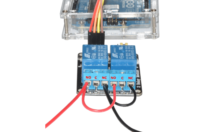
In reference to the linear actuator circuit assembly, the board comes with male headers and screw terminals unattached. This can be attached through a soldering iron. There are four holes on the board which are considerably large. These are for the wires which are not the right spacing, considering the screw terminals.
However, there are a pair of smaller holes which are the right fit.. The female power plug is then screwed onto the GND/VIN on the VNH5019. This allows easy plugging and unplugging the power supply. It is also possible to put switch to facilitate for an E-stop.
Arduino is powered via a USB. It is also possible to have a 12v5a power as well as the USB. It is important to note that the Arduino can handle 12V power, so one can get the 12v6a power supply and still power everything using the USB.
Arduino Code for Controlling Linear Actuator
There is software required to automate the functions of the setup. The first part includes making sure that the Arduino pins that trigger the relays are set to outputs.
//Use constants for the relay pins in case you need to change these later
const int relay1 = 6; //Arduino pin that triggers relay #1
const int relay2 = 7; //Arduino pin that triggers relay #2
void setup() {
//Set pinMode to OUTPUT for the two relay pins
pinMode(relay1, OUTPUT);
pinMode(relay2, OUTPUT);
}
void extendActuator() {
digitalWrite(relay1, HIGH);
digitalWrite(relay2, LOW);
}
It is crucial to test if the setup is working. In the code below, the actuator is set to extend for one second, stop for one second, retract for one second and the pause for five seconds, before repeating the process.
void retractActuator() {
digitalWrite(relay1, LOW);
digitalWrite(relay2, HIGH);
}
void stopActuator() {
digitalWrite(relay1, LOW);
digitalWrite(relay2, LOW);
void loop() {
extendActuator();
delay(1000);
stopActuator();
delay(1000);
retractActuator();
delay(1000);
stopActuator();
delay(5000);
/Use constants for the relay pins in case you need to change these later
const int relay1 = 7; //Arduino pin that triggers relay #1
const int relay2 = 6; //Arduino pin that triggers relay #2
Feel interested? More articles available on the circuits page.