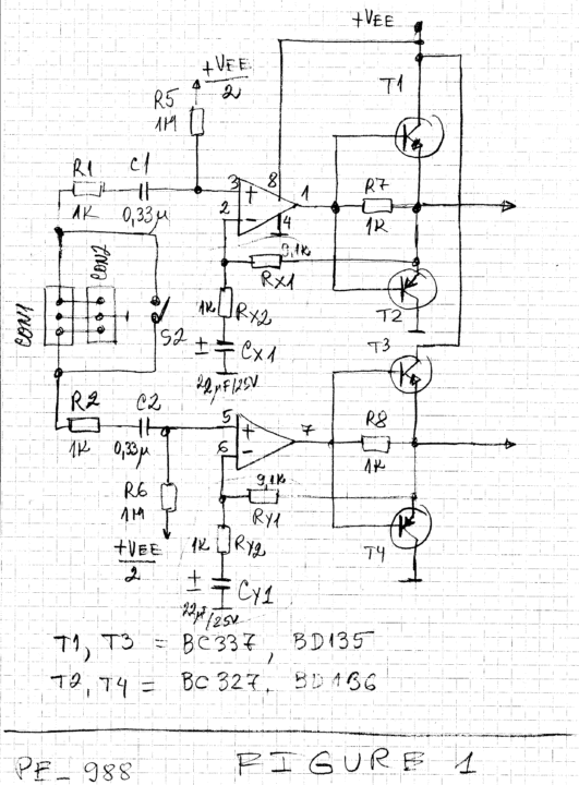
The stereo audio distribution buffer published on page 94 of the July 2013 Edition of EFY can be converted easily into stereo audio distribution amplifier.
That will add gain and will give new applications of the circuit.
Figure 1 is showing one of the possible solutions.
In order to make the conversion we should make two steps:
1/ We should cut the connections between the inverting inputs of the operational amplifiers (OAs) and the outputs of the buffers.
2/ We should add three low cost components to each channel of the amplifiers – two resistors and electrolytic capacitor.
We are adding Rx1, Rx2 and Cx1 for the first channel and Ry1, Ry2 and Cy2 for the second channel as shown on the Figure 1.
After the conversion the gain of the first channel will be
Gain1 = 1 + Rx1/Rx2
And the gain of the second channel will be
Gain2 = 1 + Ry1/Ry2
We can select any appropriate gains but we should respect
Gain1 = Gain2
In that case we have
Gain1 = Gain2 = 10
Rx1= Ry1 = 9.1KOhm
Rx2= Ry2 = 1KOhm
Cx1=Cy1 = 22uF/25V
The capacities Cx1 and Cx2 are selected according to the desired lower frequency limit of the amplifier.
Also we may get more output current and power from that circuit.
E.g. the output current can go to more than 500mA but at least two conditions should be met.
1/ The first condition is to replace BC337 with BD135 and to replace BC327 with BD136.
In all cases the transistors should have high gain, e.g. above 100.
2/ The second condition is to reduce the resistors R11-R18 to around 15-22Ohm.

These resistors depend also from the power supply and from the characteristic impedance of the driven lines.
Also these resistors are the only protection of the output of the amplifier from short circuits.
That is why R11-R18 should be no less than around 10Ohm.
If R11-R18 are below 22Ohm it is good to use 1W resistors and to have current limiting function of the power supply.
We may use the linear regulator 7824 or LM317HV to provide the power supply for the circuit.
That is limiting the maximal output current up to around 1A for both channels.
We have to say several words for the power supply of the circuit.
We can use any power supply in the range of the operational amplifiers.
E.g. with NE5532/A we can increase the power supply up to around 40V but we should take care about the power dissipations of the transistors and about the maximal working voltage of the polarized capacitors.
If we are interested in higher power supplies and higher output current small heat sinks may be needed for the transistors.


