


 Here is a simple circuit that can temporarily illuminate your cupboard or other such usually dark places where mains connection is either not possible or not worthwhile. The circuit is nothing but a battery-operated light with inbuilt auto shut-off.
Circuit and working
Fig. 1 shows the circuit of the cupboard light. It is built around a hex inverter buffer CD4049 (IC1). Inverters ‘A’ and ‘B’ along with resistors R2 and R3 constitute the Schmitt trigger. The remaining four inverters (‘C’ through ‘E’) are connected in parallel to increase the current-sinking capability.
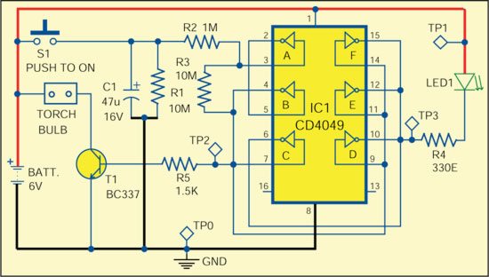
When switch S1 is momentarily pressed, the voltage across capacitor C1 rises to 6V almost instantaneously. The Schmitt trigger output goes high, which forces the output of four parallel connected inverters to go low, thus switching on LED1. At the same time, the torch bulb also glows through npn transistor T1 (BC337).

To sum up, when switch S1 is pressed, LED1 and torch bulb light up. Capacitor C1 slowly discharges through resistor R1. The moment voltage across it goes to low state, the LED and torch bulb switch off.

With the given component values, the lamp will remain ‘on’ for about two minutes. The time period can be roughly calculated as (R1×C1)/4.
Construction and testing
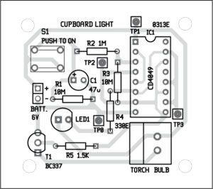
A PCB for the cupboard light is shown in Fig. 2 and its component layout in Fig. 3. Suitable connectors are provided on the PCB for input supply and torch bulb. Assemble the circuit on a PCB to save time and minimise assembly errors. Carefully assemble the components and double-check for any overlooked error.
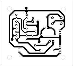
Download PCB and component layout PDFs: click here
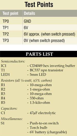
Check whether the input supply to the circuit is correct at test point TP1 with respect to TP0. The voltage at test points TP2 and TP3 should be high and low, respectively, for about two minutes once the switch is pressed.
The author is a regular contributor to EFY and has many articles published to his credit in India and abroad
