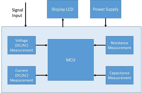
A Digital multimeter is one of the basic equipment used for Test and Measurement in electronics industries. A portable multimeter are very useful in giving accurate measurement of voltage, currents, resistances and capacitances. Digital multimeters use integrated circuits to enable digital technologies compared to analogue techniques, which enables many new features to be incorporated in the design.
Measurements in a DMM
Compared to their analogue predecessors, digital multimeters offer low-cost and many more features. Primarily the basic features that a multimeter provides are:
- Voltage (DC) measurement,
- Voltage (AC) measurement,
- Current (DC) measurement,
- Current (AC) measurement,
- Resistance measurement,
- Capacitance measurement.
In addition to that, DMM provide advanced features such as auto range, continuity check, diode and transistor check.

Using a DMM and its functioning
When purchasing a DMM for a given application, there are a number of parameters and specifications that needs to be considered before making a selection. The performance of a DMM is characterised by accuracy of measurements, range of measurement, stability, number of digits in the display etc.
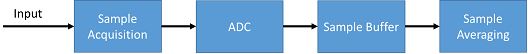
The operation of a DMM is relatively straightforward. The key process that occurs for any measurement that takes place is voltage measurement. All other measurements are derived from this basic measurement (voltage measurement). DMM uses a microcontroller and analogue to digital converter (ADC) for almost any measurement.

Most of the DMM in the market uses successive approximation (SAR) ADC or delta sigma ADC for fast operation and improved noise reduction. Although the ADC forms the key element of the instrument, there are several other blocks like sample acquisition, buffer and sample averaging which also plays an important factor in order to achieve higher resolution, accuracy and speed.
Tool for designing a DMM
PSoC is a combination of a microcontroller with programmable logic and analog to digital conversions and commonly used fixed-function peripherals. The PSoC family is made up of 8bit (PSoC 1 and PSoC 3), and 32 bit MCUs (PSoC 4 and PSoC 5). They have flash memory up to 256KB, SRAM up to 64KB and internal EEPROM up to 2KB (flash can be used to emulate EEPROM). PSoC also has a low power mode with <1µA current consumption, suitable for standby operations.
The interface and logic can be designed by the PSoC creator IDE. It has available component block for designing interface and logic like SAR ADC and Programmable gain amplifier (PGA) for analog sensors and other inputs. The character LCD and segment LCD components drives LCD/graphical LCDs. It also has a real time clock (RTC) for time measurement. It has a system clock and does not require external clock/oscillator circuitry.
PSoC creator also enables the user to make use of an ecosystem with integrated compiler tool chains, real time operating system solutions, and production programmers. Developers can create and share user-defined, custom peripherals using hierarchical schematic design. Designers can place and route components and integrate glue logic, normally located in discrete devices.
Making your DMM using PSoC
Since a DMM measures several different parameters, there are several methods of measurement in a single device. Making an equipment according to the different use case has been discussed in the next section.
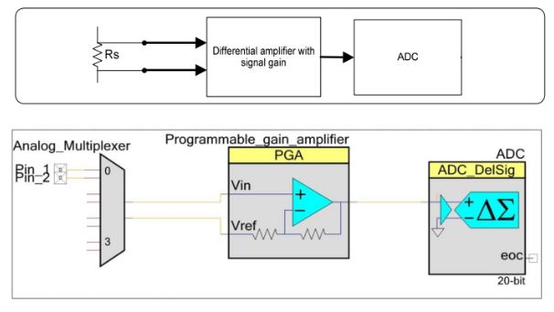
Voltage measurement: DMMs are most often used in voltage (DC/AC) measurement. A simple voltmeter can be easily implemented using PSoC. For DC measurement, the voltage of the range (+/- 5V) can directly be measured using delta-sigma ADC in the PSoC. To extend the range we have to use a resistive network to scale down the input voltage for delta-sigma ADC.
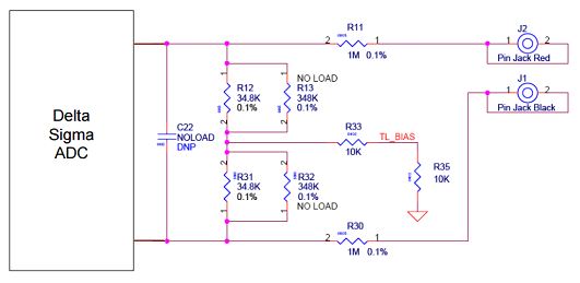
Here TL_BIAS = Vdd /2. The differential input of the resistor networks is: = (V1 – V2) / (K+1) where K=1M / 34.8k = 28.74. The resistor network successfully divides the input by a ratio of (28.74+1) = 29.74.
An implementation of voltage measurement is explained using PSoC creator components has been explained below.
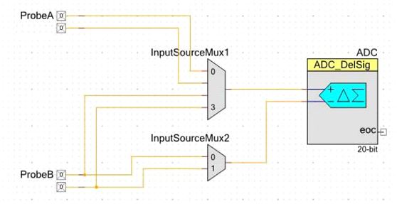
The PSoC can be programmed to add the functionality of delta-sigma ADC. It can also be configured to use PGA to measure very low (~uV) voltage with high accuracy.
However, for AC Voltage measurement a rectifier circuit is needed for AC-to-DC conversion and then fed to PSoC for root mean square (RMS) value detection.
Current measurement: Many systems require precise current measurement for variety of applications. There are different methods to measure current. One method is to use a resistor across a current output and measure the voltage across it. Now from a known value of the resistor R, the current I (I=V/R) can easily be computed from the measured voltage ‘V’.In another method, an on-chip television interface adaptor (TIA) can be configured to take current as the input and give an output voltage proportional to the input current. A delta-sigma ADC or SAR ADC can be used to measure the voltage. A simple implementation of current measurement using PSoC creator components is shown below.
However, for AC Current measurement a rectifier circuit is needed for AC-to-DC conversion and then fed it to PSoC for measurement of RMS value.
Continue making other meters using PSoC here.
Shared by Ronak Desai and Arijit Karmakar, Cypress Semiconductor