


Emergency lights commonly available in the market come with battery over-charging protection but no discharging protection. Here is a DC changeover system that protects the battery from over charging as well as over discharging. The load is powered by the regulator when mains is available and automatically shifts to DC when mains power fails. When mains power resumes, the load is again powered through the regulator and the battery starts charging.
The entire circuit can be divided into four sections: power supply, changeover, battery over-discharging and battery overcharging.
DC Changeover System
The AC mains is stepped down by transformer X1 (230V AC primary to 9V AC, 1A secondary), rectified by bridge rectifier BR1, filtered by capacitor C1 and regulated by IC 7806 (IC1) to get regulated 6V DC power supply.

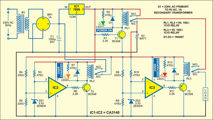
The changeover circuit is built around IC1. When AC mains is available, npn transistor T1 (BC548) conducts to energise relay RL1 (6V, 100-ohm) and green LED1 glows to indicate the presence of AC mains. At the same time, the regulator’s output feeds the load through the normally-opened (N/O) contact of relay RL1 and the normally-closed (N/C) contact of relay RL3. When the battery is charging, power LED1 glows.
When AC mains fails, transistor T1 cuts off and relay RL1 de-energises. As a result, the load is now powered by the 6V battery through the N/C contact of relay RL1. Green LED1 stops glowing to indicate that AC mains is not present, and the load works off the battery.

Battery Protection unit
The battery over-discharging protection unit is built around IC CA3140 (IC3). When the battery is over-discharged (below 5.5V), the voltage at the inverting input (pin 2) of IC3 is higher than the voltage at the non-inverting input (pin 3). Thus the output of IC3 is low and transistor T3 is cut-off. The 5V, 100-ohm relay (RL3) de-energises and the load disconnects from the battery to protect it from over-discharging. At the same time, LED3 glows to indicate that the battery is over-discharged.
When AC mains resumes, the 6V battery starts charging through the N/C contacts of relay RL2. As soon as the battery voltage reaches above 5.5V, the output of IC3 goes high to energise relay RL3 through transistor T3 (BC548) and the load now connects to the regulator’s output.
Battery protection circuit
The battery over charging protection unit is built around another IC CA3140 (IC2). When AC mains is available and the battery voltage is below 6.6V, the voltage at the inverting input (3.3V) of IC2 is higher than the voltage at the non-inverting input (pin 3). Thus the output of op-amp IC2 is low, which cuts off transistor T2 and the relay remains de-energised. In this condition, the battery keeps charging through the N/C contacts of the relay. As soon as the battery voltage reaches 6.6V, the output of IC2 goes high and relay RL2 energises through transistor BC548 (T2). LED2 glows to indicate the over-charging status of the battery.
Diodes D1 through D3 are used as free-wheeling diodes to protect the chattering of respective relays from the back e.m.f.
Construction & testing
Assemble the circuit on any general purpose PCB. Here we have used a 6V/4Ah battery. The time taken by the battery for charging completely depends upon the ampere rating and the voltage rating of the transformer.
The article was first published in May 2006 and has recently been updated.

hello
thank you for this very useful circuit.
i have an egg incubation controller that works with 5V/1A and controlls two heater, two fan and one motor.
in this circuit you have one output but i need to have more than one. One +5V/1A, One +9V, two +12V.
if it may i want to ask you help me to customize this circuit according to my purpose.
and my last question is: the Resistors and Zener diodes are in what power? and what is BR1 Diodes?
Best Regards.
thanks
You are most welcome.
lower cutoff not possible never, because when the battery voltage reached 5.5v, the relay turned off and disconnected the load from battery. As a result the battery voltage increases suddenly and relay turned ON.
I think there is a mistake in the explanation for the discharge section. If the base of T3 is low, then the tranzistor conducts and the relay is energized.