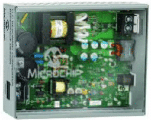
The 200W DC/DC LLC resonant converter reference design simplifies the design process. It operates over a wide input voltage range and delivers high efficiency.

Among the various DC/DC converter topologies available today, designers typically choose one based on a balance of conflicting requirements. Efficiency, power density (i.e., the converter’s size), and cost are the primary considerations in the design process. The resonant converters, specifically LLC resonant converters, offer all the desired features. They provide a compact and highly efficient design. Additionally, their capability to maintain a regulated output voltage over a wide input voltage range helps lower the overall system cost. 200W DC/DC LLC resonant converter reference design by Microchip simplifies the design process.
The reference design operates over a wide input voltage range of 350-420 Vdc, with a nominal input of 400V, delivering a 12V DC output while maintaining high-voltage isolation between the primary and secondary sides. High efficiency is achieved through Zero Voltage Switching (ZVS) on the half-bridge converter and Zero Current Switching (ZCS) on the synchronous rectifier. Using a synchronous rectifier instead of the traditional full-wave rectifier further enhances efficiency. The reference design utilizes Microchip’s digital power conversion dsPIC for adaptive control of the half-bridge converter and synchronous rectifier.
This design uses a single dsPIC33EP / dsPIC33FJ “GS” digital-power DSC from Microchip, providing full digital control of power conversion and system management functions. Using dsPIC33EP / dsPIC33FJ ‘GS’ devices efficiently allows designers to easily and cost-effectively create products using advanced switching techniques, such as LLC, that reduce switching losses and achieve efficiencies as high as 95%.
Applications utilizing the LLC converter can benefit from two main features: very low switching losses resulting in high efficiency and the ability to control the output voltage under all load and line conditions. The system features low power consumption at no load, programmable soft-start functionality, and comprehensive monitoring and protection for voltage, current, and temperature. It also includes full digital control and control of both primary and secondary MOSFETs.
The switching circuit utilizes a half-bridge topology, allowing the output voltage to oscillate between 0V and a nominal 400V dc. While a full-bridge circuit could also have been used, the half-bridge was chosen for its simplicity and fewer components. The resonant tank circuit consists of a capacitor, an inductor, and an isolating transformer. The transformer’s magnetizing inductance effectively replaces the required second inductor; sometimes, even the primary inductor may be integrated into the transformer. Such a configuration minimizes the converter’s size, cost, and complexity. On the secondary side, a synchronous rectifier enhances the system’s overall efficiency.
Microchip has tested this reference design. It comes with a bill of materials (BOM), schematics, assembly drawing, printed circuit board (PCB) layout, and more. The company’s website has additional data about the reference design. To read more about this reference design, click here.


