 Light Fidelity (Li-Fi) is a new paradigm in wireless communication. In this article, we describe the design of a Li-Fi dongle (transmitter) and speaker (receiver) for audio and music applications. The proposed system is a replacement for wired speakers that plays audio signals received through light. The dongle can be designed for less than ₹ 350.
This Li-Fi system scores over Bluetooth speakers as follows:
1. The LED light in a room is used not just to light up the room but also to play music, thus giving benefits of both the worlds. Also, LED bulbs use 85 per cent less energy than incandescent bulbs and last up to 20 times longer, whereas majority of Bluetooth modules are battery-powered and generally last a year or two only before they need replacement. Hence the proposed system is energy-efficient over Bluetooth version.
2. You can receive Li-Fi data as long as you are in the range of the light being emitted by the LED light source. Hence, the range depends on the strength of the light being emitted.
3. Connectivity needs to be established between the Bluetooth transmitter and the receiver, whereas with Li-Fi any user can receive data and play music on his speaker by simply keeping the receiver in the range of LED light source.
4. The proposed system can be used with any audio system by just connecting the Li-Fi dongle to its audio output jack, with no pairing and connectivity requests. This overcomes the problem of connecting a Bluetooth speaker to audio systems that do not have USB port and Bluetooth support, which is otherwise a tougher task.

5. The proposed Li-Fi dongle and speaker costs lower than a Bluetooth dongle and speaker.
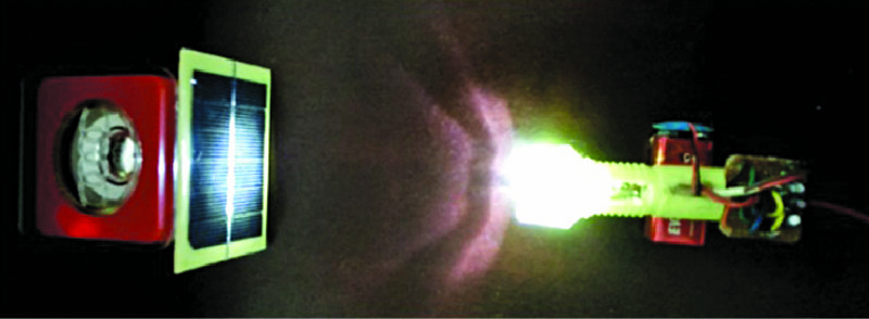
The proposed concept is illustrated in Fig. 1. It uses a Li-Fi dongle to transmit audio signals from a source such as mobile phone, and a Li-Fi speaker with solar cells at the receiver end to receive audio signals without wires.
The proposed Li-Fi dongle is connected to the audio jack output available on mobile phones. It has an LED through which audio/music signals are transmitted as light signals. These light signals are captured by the Li-Fi speaker through the solar cell array. The authors’ prototype is shown in Fig. 2.
Circuit and working
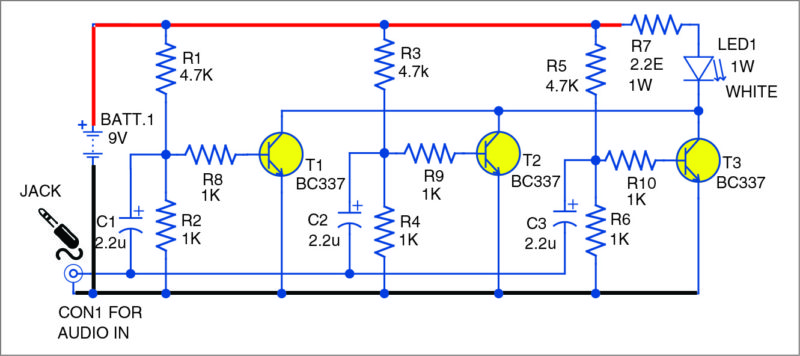
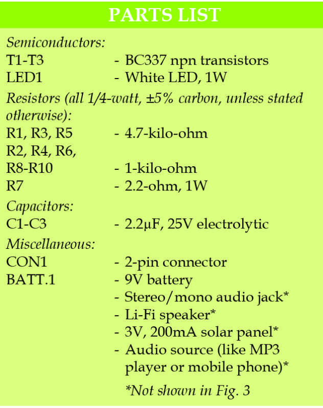
Fig. 3 shows the circuit of the Li-Fi dongle. It uses three common-emitter (CE) amplifiers connected in parallel to amplify the input audio signal. The Li-Fi speaker is designed by connecting the output of a 3V, 200mA solar cell array to a speaker’s audio input. For this, connect the terminals of the solar panel to a 3.5mm female audio socket. Then, connect the 3.5mm audio jack from the speaker to the female socket.
During testing, Boom KBS M2 speaker was used. It is available on Flipkart.
However, you need not buy the exact speaker or Li-Fi speaker. Any speaker with an inbuilt amplifier will do the job. You can modify the same to work as a Li-Fi speaker by interfacing a solar panel to it. After adjusting the band equaliser in the audio source and the distance between the solar panel and the light source, you can get almost noise-free sound from the speaker.
The maximum distance/range between the transmitter and receiver depends on the number of amplifier stages. For a three-stage CE amplifier, the maximum distance is about two metres with LED illuminance of 13,842.00 lux at the receiver side. For a five-stage CE amplifier, the distance can be up to 2.6 metres with LED illuminance of 17,382.00 lux. It was observed that as you increase the number of CE amplifier stages connected in parallel in the transmitter circuit, the intensity of LED light also increases, which, in turn, increases the maximum distance up to which the sound is audible from the Li-Fi speaker.
This circuit finds the following applications:
1. Stream music from a mobile phone, MP3 player, laptop, tablet or other mobile audio system wirelessly to Li-Fi speakers. A camera flashlight can be used for the purpose.
2. Transmit audio signals from a microphone on the dais to speakers in an auditorium using pre-installed LED lights.
3. Use reading lights in buses, trains, cars and airplanes to play melodious music wirelessly on Li-Fi speakers.
The system can be used in offices, hotels, auditoria, etc, where bright lighting is required throughout the day.
Construction and testing
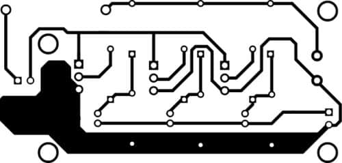
An actual-size PCB layout for the Li-Fi dongle is shown in Fig. 4 and its components layout in Fig. 5. After assembling the circuit on the PCB, enclose it in a suitable box and mount LED1 on front panel of the box. Connect the dongle to an audio source like mobile phone.
When you play the song, the white LED (LED1) will start blinking. Focus the LED light towards the solar panel. You should be able to hear the song from the speaker. Adjust the distance between the light source and the solar panel until you hear clear sound from the speaker.

Download PCB and component layout PDFs: click here
Also, check the step-by-step guide to designing a Li-Fi system for wireless data transfer.
This article was first published on 18 Oct 2017.




In the li-fi dongle circuit if we use 5w led instead of 1w, then what modification should be made in the circuit ?
sir
i am aware of the solar LiFi internet and i want to know if my 3 watts solar panel with the USB integrated can also be used as a photo detector to receive and transmit binary data for internet browsing kindly help out on this
kindly help with detailed step by step process in creating and transmitting usb internet data using LiFi circuit in my home
sir
kindly help me with detailed step by step process in creating and configuring the LiFi internet
i desire both the analogue and digital details
for the LiFi internet transmitter and receiver
help !!!!
sir
what kind of operational amplifier(op amp) or integrated circuit(IC) is best for the construction of transimpedance (transfer impedance amplifier) with two female usb port one for a solar panel photodetector in one and one out that feeds the desktop system in a LiFi internet receiver dongle.
is it posible to use two op amps one for initial voltage boost and one for final voltage boost to increase the desired speed of my internet
what is the relationship that exist in byte/seconds between the parameters or is this bit/seconds produced in the data log of the desktop motherboard on receiving the incoming amplified voltage
kindly briefly explain
expecting your expose soonest
I really wanted to know whether we have to use 3V, 200mA solar panel compulsorily. Because i cannot find it in my area. Can 6v, 200ma or 3v,150ma be used instead?
What’s the use of R8 resistor which is fed into the base of a T1 of bc337 transistor?
Bc337 is using as amplifier so R8 is its base resistance
ohms law and current gain of a transistor has to consider while design a transistor in a circuit, or else the efficiency of device will be much lower than the actual. This circuit will work but the resistance designed to the transistor base and collector is not with respect to the points i mentioned so efficiency will be much smaller than the actual.
Sir,can u send me the designs of this BC337 transistor?
U r jezuz
sir is it working..bcoz i did that at my home..bt the LED is not blinking..so that could u help me out..
Hi Mukesh, I am the original designer of this circuit. The LED should not blink it should stay solid bright. Li-Fi is here to provide two things:1) Room lighting 2) Data transmission via room lighting.
Regards
Hi Sir.
Have you the pcb scheme in gerber file format?
Thanks
Please contact on [email protected] for PCB gerber file of this circuit
Can we transmite the lm35 temp ic’s output using this circuit by coñnecting the output of this ic at the place of audio in point????
What is the data transfer rate of this self-made dongle and the modulation technique used?
While doing this project our dongle circuit is getting short circuited . could you help us please. We have checked the connections as well. Please help
For our project we applied the same circuit however the dongle circuit is getting short circuited. Sir can you please help me for the same we have checked the circuit no connection seems to be wrong.
sir can we use photodiode circuit instead of solarcell.